Command issuing apparatus for high-speed serial interface

a high-speed serial interface and command issuing technology, applied in the direction of instruments, computation using denominational number representation, multi-programming arrangements, etc., can solve the problems of insufficient command execution speed, inability to fully exploit the transmission performance of the target apparatus, and difficulty in including a cpu offering sufficient speed performance in an audiovisual apparatus. achieve the effect of high response performan

Inactive Publication Date: 2006-10-24
COLLABO INNOVATIONS INC
View PDF15 Cites 2 Cited by
  • Summary
  • Abstract
  • Description
  • Claims
  • Application Information

AI Technical Summary

Benefits of technology

The present invention provides a way for a command issue device to have very fast response times when starting new tasks. This happens without actually programming any specific controls into the system first.

Problems solved by technology

The technical problem addressed in this patent is how to improve the transmission performance of a high-speed serial interface, specifically for use in audio visual devices like set top boxes, while utilizing existing hardware components without adding significant costs.

Method used


Image

  • Command issuing apparatus for high-speed serial interface
  • Command issuing apparatus for high-speed serial interface
  • Command issuing apparatus for high-speed serial interface

Examples


Embodiment Construction

[0042]Embodiments of the present invention will be described below in detail with reference to the accompanying drawings. However, the following description does not limit the technical scope of the present invention.

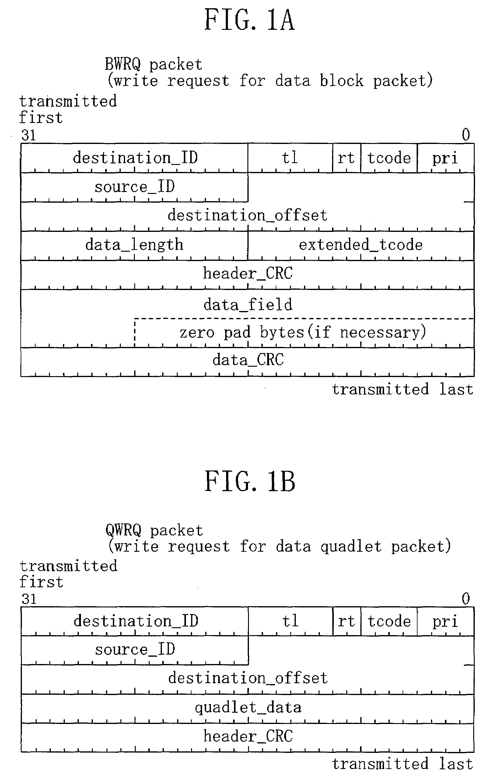
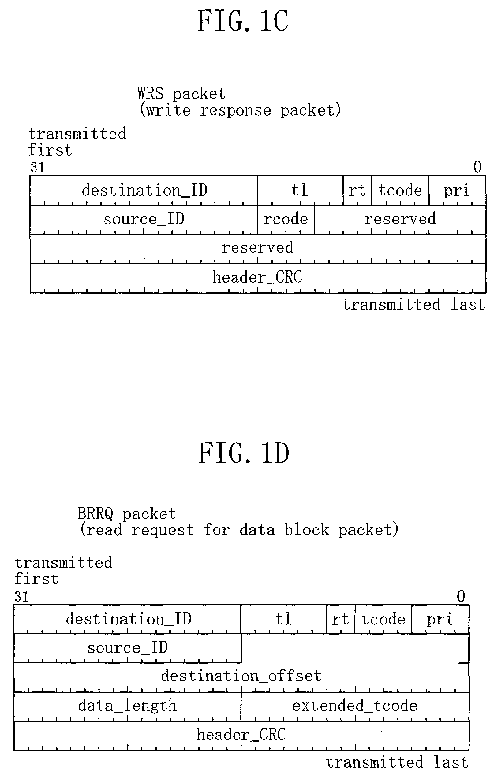
[0043]FIGS. 1A through 1E show structures of some of the asynchronous packets defined in IEEE 1394. IEEE 1394 defines request packets for requesting operations and response packets for returning the results of the operation requested with the request packets. When one of these packets is received, an acknowledge (ACK) packet indicating the state of the reception of the packet is returned to the requesting device. The ACK packet indicates a state such as “ack_complete”, which indicates the completion of an operation, “ack_pending”, which indicates that a request has been received and a requested operation is being processed, and “ack_busy”, which indicates a retransmission request (ack_busy). A request packet and a response packet are usually used in pairs.

[0044]FIGS. 1A...


PUM


Abstract

In order to reduce load placed on a CPU (central processing unit) in providing SBP-2 (serial bus protocol 2) initiator capability, provided are a sequence control circuit activated by the CPU for controlling a command issue sequence, a packet processing circuit for assembling operation request blocks (ORB) into a transmission packet and extracting a status from a received packet; buffer for storing a command ORB provided by the CPU; a buffer for storing a management ORB provided by the CPU; a buffer for storing a status received for an issued management ORB and providing the status to the CPU; and a buffer for command for storing a status received for an issued command ORB and providing the status to the CPU.

Description


Claims


Application Information

Patent Timeline
Owner COLLABO INNOVATIONS INC
Why Eureka
Try Eureka