Button

a button and button technology, applied in the field of buttons, can solve the problems of troublesome operation, inability to completely solve the difficulty of fastening and unfastening the button through the buttonhole, and the difficulty of fastening and unfastening the button, so as to reduce manufacturing and assembly processes, the effect of easy bending

Inactive Publication Date: 2006-10-31
YKK CORP
View PDF14 Cites 4 Cited by
  • Summary
  • Abstract
  • Description
  • Claims
  • Application Information

AI Technical Summary

Benefits of technology

[0014]In the present invention, in order to fasten the button, the insert portion of the extending portion is inserted into the buttonhole and the insert portion projected from the buttonhole is pinched to turn the button body. When the button body is turned, the guide extending arcuately or linearly from the insert portion toward the button body guides the button body to the buttonhole, and thus the button body can be smoothly guided to the buttonhole. By turning the button body by a predetermined angle, e.g. 180 degrees, the button comes out from the buttonhole, being fastened into the buttonhole.
[0034]According to the present invention, since the cover including the extending portion, the insert portion and the guide is molded out of plastic, especially the extending portion is easy to bend so that the button can be fastened even more easily. Furthermore, the cover and the connector are integrally molded out of plastic, manufacturing and assembly processes can be reduced.

Problems solved by technology

When a denim etc. is used for the jeans, it is difficult to fasten and unfasten the button through a buttonhole due to its stiff texture.
However, when the fabric is thick at an attachment position of the button and a turnback portion around the buttonhole, difficulty in fastening and unfastening the button cannot be completely solved.
In the applications disclosed in the References 1 and 2, since the buttoning tool is inserted into the buttonhole to hook the button for fastening the button, the operation is bothersome.
Moreover, a user needs to carry the buttoning tool all the time in order to use it whenever necessary, thus it is not practical.
In order to unfasten the button, since the base end side of the button is passed through the buttonhole while keeping the base end side pushed, unfastening operation can be difficult depending on a width (size) of the base end.

Method used


Image

  • Button
  • Button
  • Button

Examples


first embodiment

[First Embodiment]

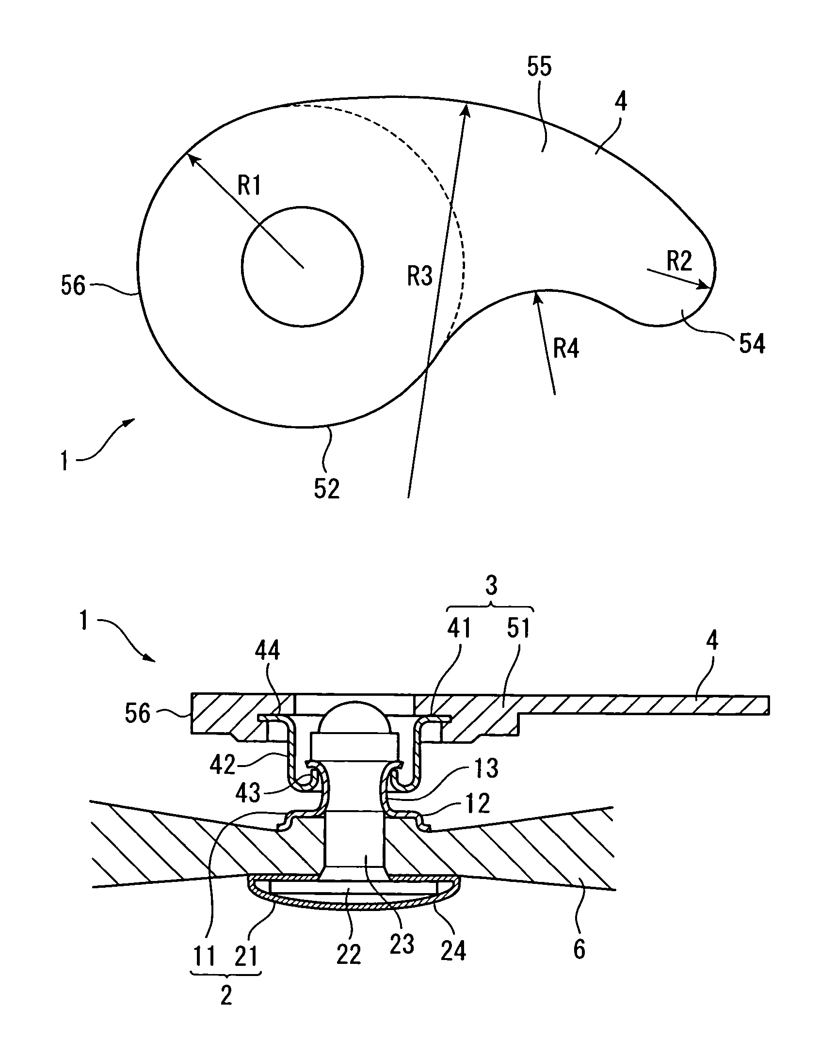
[0055]FIGS. 1A and 1B show a first embodiment with a button of the present invention applied to the button for jeans, and FIG. 1A is a plan view while FIG. 1B is a sectional view. As shown in FIGS. 1A and 1B, the button of the first embodiment has a button body 1 including an attachment to a first fabric 6 and an extending portion 4 extending from the button body 1 in a predetermined direction, and is so formed that the button can be fastened into and unfastened from a buttonhole provided to a second fabric (not shown).

[0056]The button body 1 includes an attachment member 2 forming an attachment to the first fabric 6, and a cover member 3 turnably and swingably held on a front side of the attachment member 2. In other words, the cover member 3 is turnably and swingably held to the first fabric 6 through the attachment member 2.

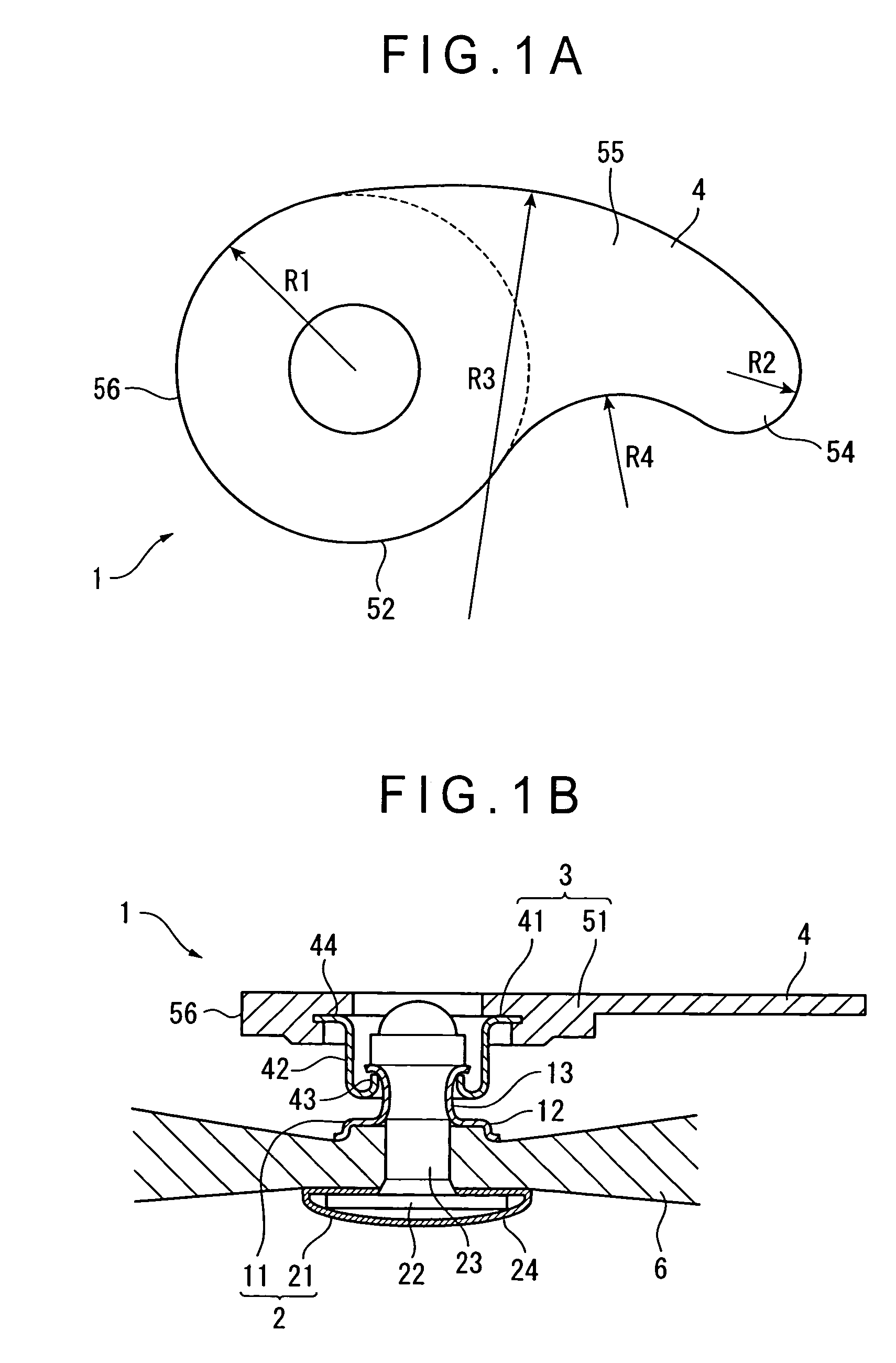
[0057]The attachment member 2 has a front side fixing tube 11 applied to the front side of the first fabric 6, and a back side fixture 21 pe...

second embodiment

[Second Embodiment]

[0077]FIG. 12 shows a button according to a second embodiment of the present invention. The button in the second embodiment differs from the button in the first embodiment only in its cover member.

[0078]The cover member 3A of the present embodiment has a metal connector 41A as a connecting member that is turnably held by the attachment member 2 (the front side fixing tube 11), and a die-cast cover 51A engaged with the front side of the connector 41A.

[0079]According to the present embodiment, the cover 51A including the extending portion 4, the insert portion 54, the guide 55 and the widening member 56 is formed by die-casting. Since the die-cast cover 51A can also function as a die caulking and deforming the back side fixture when the back side fixture is caulked from the opposite side of the attachment member 2 with a fabric sandwiched therebetween, it can be easily attached to a fabric.

third embodiment

[Third Embodiment]

[0080]FIG. 13 shows a button according to a third embodiment of the present invention. The button in the third embodiment differs from the button in its first embodiment only in the cover member.

[0081]The cover member 3B has a connector 41B as a connecting member turnably held by the attachment member 2 (front side fixing tube 11), and a cover 51B provided on the front side of the connector 41B, and the connector 41B and the cover 51B are integrally molded by metal plate press working. The connector 41B and the cover 51B are processed to have the edge rolled up toward inside (for safety).

[0082]According to the present embodiment, since the cover 51B including the extending portion 4, the insert portion 54, the guide 55 and the widening member 56 is integrally molded with the connector 41B by metal plate press working, it can be processed easily with low cost.


PUM


Abstract

A button has a button body (1) including an attachment to a fabric (6) and an extending portion (4) extending from the button body (1) in a predetermined direction. The button body (1) is turnably fixed to the fabric (6) by the attachment. The extending portion (4) has an insert portion (54) adapted to be inserted into a buttonhole, a guide (55) extending arcuately from the insert portion (54) toward the button body (1), the guide (55) guiding the button body (1) to the buttonhole when the button body (1) is turned.

Description

BACKGROUND OF THE INVENTION[0001]1. Field of the Invention[0002]The present invention relates to a button used for jeans, etc. More specifically, a button being attached to a first fabric and capable of being fastened into or unfastened from a buttonhole formed on a second fabric.[0003]2. Description of Related Art[0004]Conventionally, a metal button has been used for jeans. When a denim etc. is used for the jeans, it is difficult to fasten and unfasten the button through a buttonhole due to its stiff texture.[0005]To solve the disadvantage, a button swingable to a member attached to a fabric, i.e. a swing button has been developed. However, when the fabric is thick at an attachment position of the button and a turnback portion around the buttonhole, difficulty in fastening and unfastening the button cannot be completely solved.[0006]With such background, some patent applications have been conventionally suggested relating to a buttoning tool facilitating fastening and unfastening o...

Claims


Application Information

Patent Timeline
Patent Type & Authority Patents(United States)
IPC IPC(8): A44B1/18A44B1/00A44B1/08A44B1/20
CPCA44B1/08A44B1/20Y10T24/3679Y10T24/36
Inventor KIMOTO, TAKASHI
Owner YKK CORP
Why Eureka
Try Eureka