Ratchet scissors

a technology of ratchet scissors and ratchets, which is applied in the field of ratchet scissors, can solve the problems of short cutting time, limited number of ratchet teeth b>32/b>, and the disadvantages of the prior art, and achieve the effect of smooth, stepwise cutting of the pip

Inactive Publication Date: 2006-10-31
HUANG YONG SHENG
View PDF6 Cites 84 Cited by
  • Summary
  • Abstract
  • Description
  • Claims
  • Application Information

AI Technical Summary

Benefits of technology

[0006]It is therefore an object of the present invention to provide a pair of ratchet scissor

Problems solved by technology

However, the prior art suffered from a couple of disadvantages.
Further, the number of the ratch

Method used


Image

  • Ratchet scissors
  • Ratchet scissors
  • Ratchet scissors

Examples


Embodiment Construction

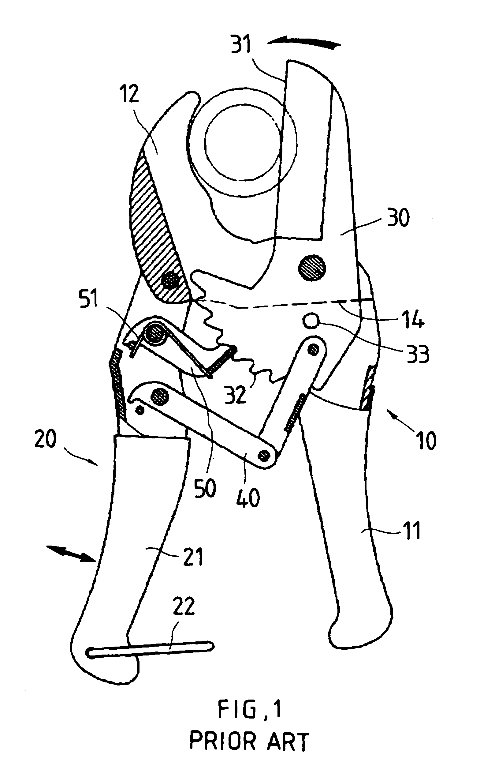
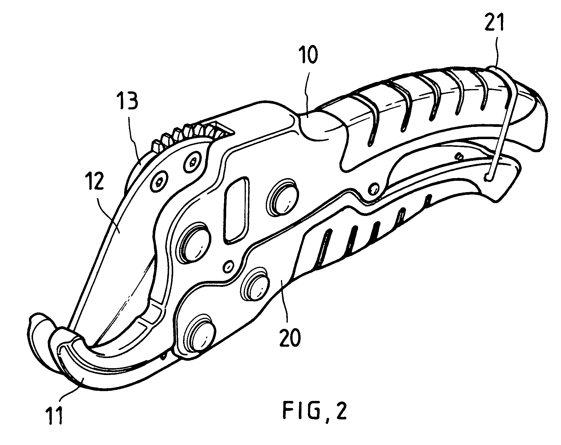
[0016]Referring to FIGS. 2, 3, 4, and 5, a pair of ratchet scissors in accordance with a preferred embodiment of the invention comprises a movable second handle unit 20 of substantially U-section including a pivotal ring 22 provided at its rear open end, and an internal projection 22 provided at its front end; a stationary first handle unit 10 including a substantially U-shaped handle portion having a plurality of parallel slots thereon such that the ring 22 is adapted to dispose in one of the slots for fastening the first and second handle units 10 and 20 together in a storage state, an extended, bifurcated jaw 11 with either portion having an inner curved edge, a blade 12 disposed in the jaw 11 and pivotably connected to a joining portion of the handle unit 10 and the jaw 11 by means of a plurality of fasteners 14, the blade 12 having a cutting edge 121 a plate-shaped pivotal member 13 disposed in the jaw 11 and including a tab 131 on one surface, and a series of teeth 132 formed ...


PUM


Abstract

Provided is scissors comprising a movable first handle unit; a stationary second handle unit including a bifurcated jaw, a pivotal blade in the jaw, a spring biased pivotal plate member in the jaw and including teeth, a gear and ratchet wheel assembly, and a spring biased pivotal pawl; and a spring biased lever including a pawl member engaged with the ratchet wheel. Continuously pivoting the first handle unit about the second handle unit by moving the first handle unit alternately back and forth in each action of pivoting the first handle unit toward the second handle unit will pivot the first and second protrusions counterclockwise, rotate the gear and ratchet assembly clockwise, and pivot the teeth counterclockwise to cut a pipe anchored in the mouth.

Description

BACKGROUND OF THE INVENTION[0001]1. Field of Invention[0002]The present invention relates to scissors and more particularly to a pair of ratchet scissors for smoothly, stepwise cutting a pipe (e.g., water pipe) without causing deformation in a labor saving manner.[0003]2. Related Art[0004]A conventional pair of scissors for cutting pipe (e.g., water pipe) is shown in FIG. 1. The scissors comprises a first assembly 10 including a stationary handle unit 11, a stationary jaw 12 having an inner curved edge, and a shoulder 14; a second assembly 20 including a movable handle unit 21 and a pivotal ring 22 provided at an open end of the handle unit 21; a movable jaw 30 pivotably connected to an intermediate portion of the first assembly 10 and including a blade 31 formed on an inner edge facing the stationary jaw 12, a series of ratchet teeth 32 formed opposite the blade 31, and a raised stop 33 proximate the shoulder 14; a toggle link 40 interconnected a forward portion of the handle unit ...

Claims


Application Information

Patent Timeline
IPC IPC(8): B23D21/00
CPCB23D21/06B26D3/169
Inventor HUANG, YONG SHENG
Owner HUANG YONG SHENG
Why Eureka
Try Eureka