
Friction drive conveyor

a conveyor and friction drive technology, applied in conveyors, rope railways, roads, etc., can solve problems such as inability to reliably drive carriers, and achieve the effects of simple structure, convenient and efficient operation, and simple structur

Active Publication Date: 2006-10-31
DAIFUKU CO LTD
View PDF5 Cites 15 Cited by
  • Summary
  • Abstract
  • Description
  • Claims
  • Application Information

AI Technical Summary

Benefits of technology

[0006]One object of the present invention is to provide a friction drive conveyor that can solve the foregoing problem. In other words, the object of the invention is to simplify the driving control of the frictional wheels of the conveyor, thereby reducing the cost of the conveyor.

Problems solved by technology

Specifically, in the disclosed conveyor, if the linear frictional surface of any carrier is present between two adjacent frictional wheels, the carrier may not be driven reliably when the forward frictional wheel starts rotating.

Method used


Image

  • Friction drive conveyor
  • Friction drive conveyor
  • Friction drive conveyor

Examples


first embodiment

[0091]The control box 24 provided for each drive unit 23 in the first sections A1 of the linear paths 50 is identical with the control boxes 24 of the first embodiment and operates as described earlier with reference to the flowchart shown in FIG. 8. Accordingly, no description will be provided of the running control of the carriers 1 in the first path sections A1.

[0092]FIG. 15 is a flowchart of the operation of the control circuits of the control boxes 53 for the second sections A2 of one linear path 50 and the horizontal curved path 51. If the frictional wheel 30 of at least one drive unit 23 of any one second path section A2 is in compressive contact with any one frictional surface 15 of any one carrier 1, the associated limit switch 33a is on (S7 in FIG. 15). In this case, on the basis of the load bar sensor on-off OR signal input from the associated OR circuit box 54 through the associated signal cable 56 into the associated control box 53, this control box transmits no start s...

second embodiment

[0104]The switching circuit 61 may be either electronic or mechanical. The embodiment shown in FIGS. 16A, 16B, 17 and 18 might be applied to the relationships among the control box 53 of each second path section A2 and the control boxes 24 of the two adjacent first path sections A1 of the second embodiment shown in FIGS. 13–15.

[0105]The present invention is not limited to the preferred embodiments. The carriers 1 do not need to be driven by frictional wheels 30 all along the track. The carriers 1 may be driven by frictional wheels 30 only along one or more sections of the track and by other drive means along another or other sections of the track. The friction drive conveyor according to the present invention is not limited to a conveyor including carriers 1 that run over a floor, as shown in the drawings, but may be any other friction drive conveyor. The friction drive conveyor may be a trolley conveyor including carriers that run under a ceiling. The friction drive conveyor may be...


PUM


Abstract

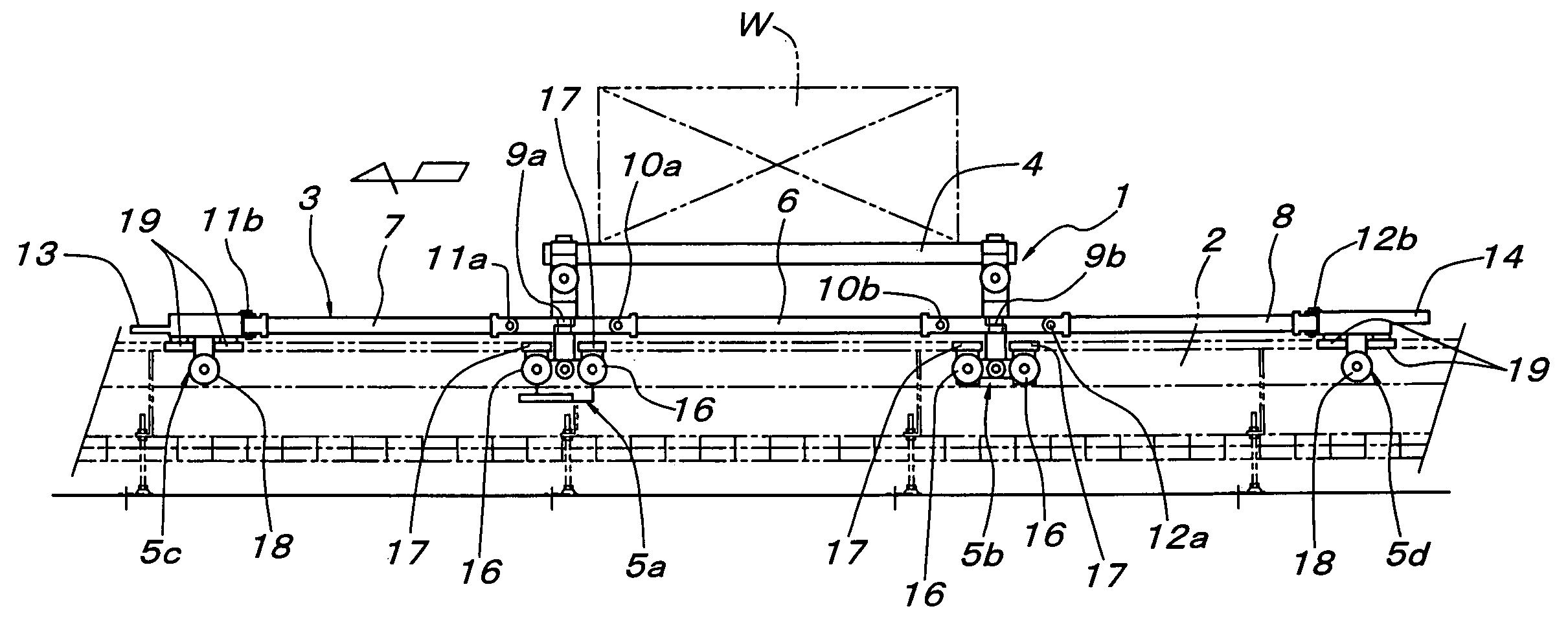
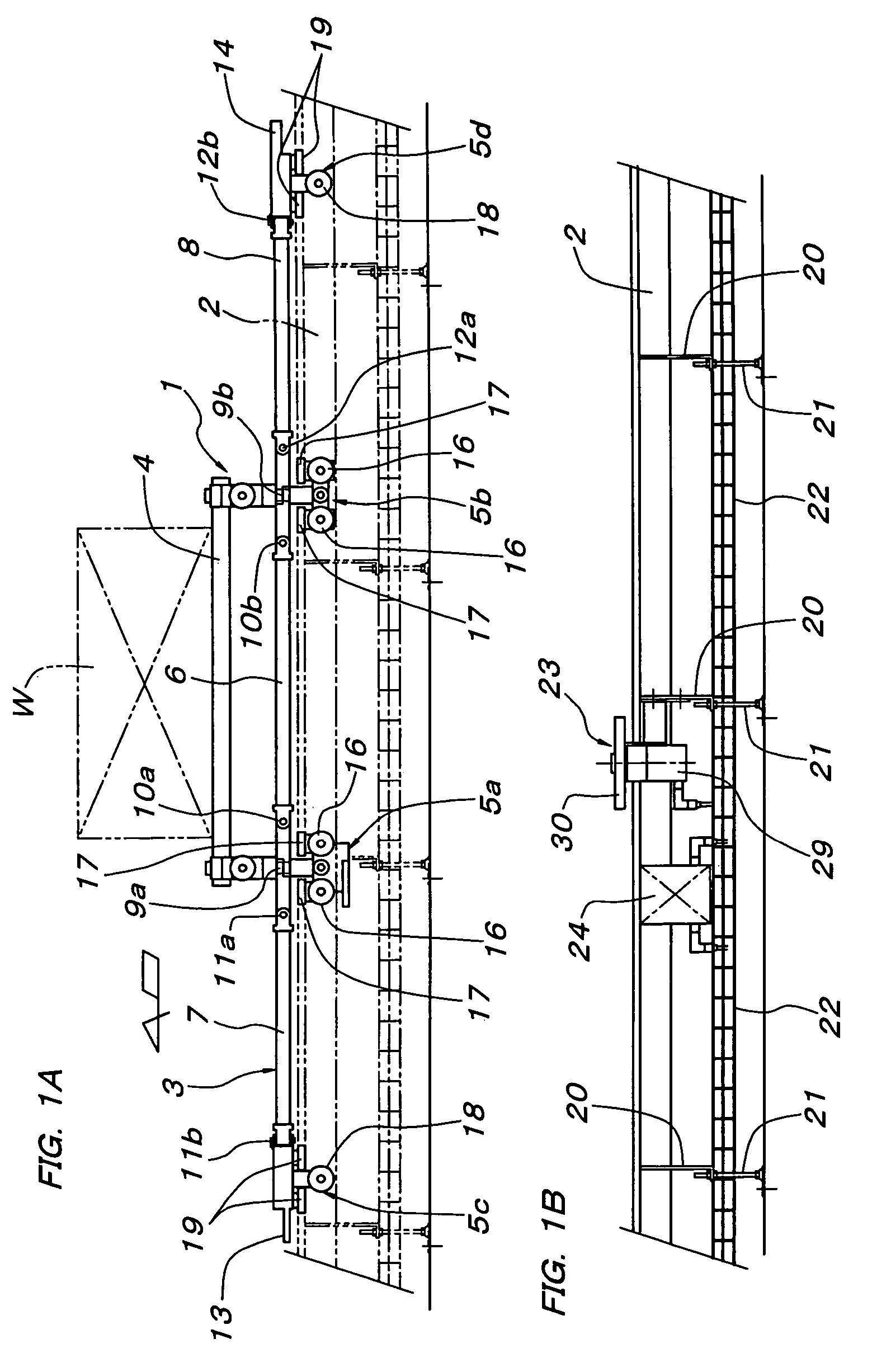
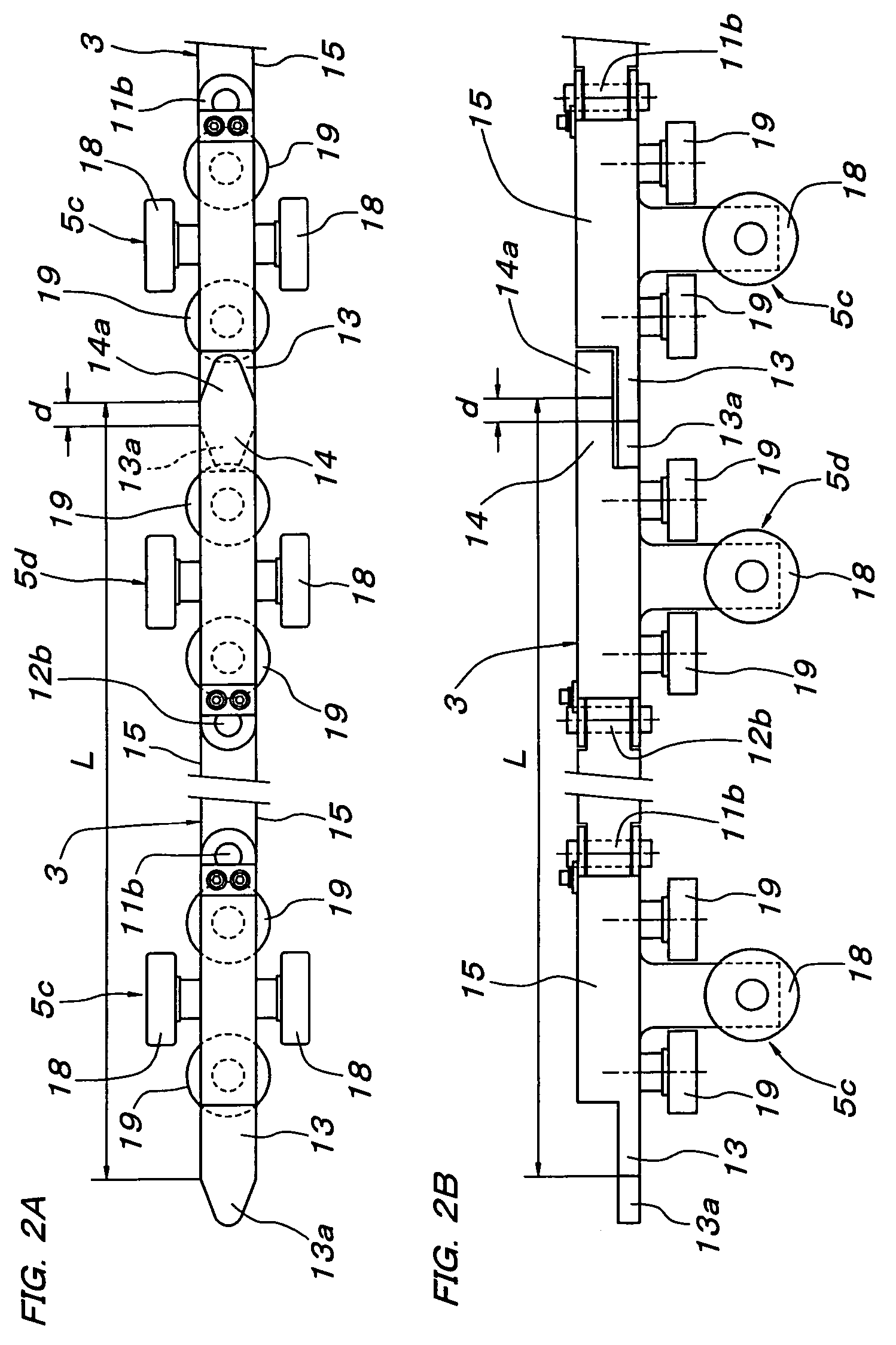
The present invention relates to a friction drive conveyor including carriers 1, which can be propelled along a track by frictional wheels 30 fitted along the track. Each frictional wheel 30 can be driven by a brakeless motor 29. A sensor 32 senses whether each frictional wheel 30 is in contact with any one frictional surface 15 of the carriers 1. The track includes a section along which the frictional wheels 30 are supported at regular intervals equal to or slightly shorter than the total length L of the frictional surfaces 15 on each side of each carrier 1. On the basis of a signal output from each sensor 32, a controller 24 so controls the associated brakeless motor 29 as to start rotating the associated frictional wheel 30 in contact with any one frictional surface 15 when the forward next wheel 30 gets free of the frictional surfaces 15, and as to stop driving the frictional wheel 30 having got free of the frictional surfaces 15.

Description

FIELD OF THE INVENTION[0001]The present invention relates to a friction drive conveyor including carriers, which can be propelled along a track by frictional wheels fitted along the track.PRIOR ART[0002]A friction drive conveyor of this type is disclosed in Japanese Unexamined Patent Publication No. 2003-54731. This conveyor includes a carrier that runs in a running direction along a track. The carrier includes a load bar extending in the running direction. The load bar has a linear frictional surface formed on one side except for both end portions. Drive units are fitted along the track and each include a frictional wheel for rotating in contact with the frictional surface. The end portions of the load bar are tapered (arcuate or V-shaped) for smooth contact with the frictional wheels and another reason. The frictional wheels are spaced at regular intervals equal to the whole length of the load bar, which is longer than the whole length of the frictional surface. In other words, th...

Claims


Application Information

Patent Timeline
IPC IPC(8): B61B3/00E01B25/22B61B13/12B62D65/18B65G35/06
CPCB61B13/127B62D65/18B65G35/06B65G2203/0283B65G2203/047
Inventor NISHIHARA, SHIGEYOSHIMURAKAMI, HIROYUKIMIYOSHI, KAZUHIKOMORITA, SUSUMUIBA, TOSHIYUKIOBATA, JUNJI
Owner DAIFUKU CO LTD
Learn More