Wet barrel fire hydrant flow preventer

a technology of flow prevention apparatus and fire hydrant, which is applied in the direction of drawing-off water installation, functional valve type, transportation and packaging, etc., can solve the problems of high probability of such events, damage to pipes and valves in the system, and water loss considerable, so as to reduce the effect of water hammer, and simple installation

Active Publication Date: 2006-10-31
MUELLER INT LLC
View PDF16 Cites 14 Cited by
  • Summary
  • Abstract
  • Description
  • Claims
  • Application Information

AI Technical Summary

Benefits of technology

[0012]The present invention provides a fluid flow prevention apparatus for a wet barrel fire hydrant which is simple to install and relatively inexpensive, yet will effectively cut off water flow without causing water hammering of the system's elements. The fluid flow prevention apparatus includes a valve member for closing the flow passageway of a pipe connected to a wet barrel fire hydrant. The valve member is positioned in-line with the flow passageway of the pipe and is operably movable from an open to closed position upon damage to the hydrant. An adjustable damping member controls the rate of closing of the valve member to reduce the effects of water hammer when the valve member closes.

Problems solved by technology

Because wet hydrants are constantly supplied with water, however, damage to the hydrant can result in a considerable loss of water before the damaged hydrant is discovered and repaired.
Unfortunately, the probability of such events occurring is quite high due to the standard location of hydrants adjacent the street curbs to facilitate rapid access by fire department personnel in the event of a fire emergency.
With these and other devices, however, damage to the pipes and valves in the system can occur as a result of the high pressure that these elements experience due to the sudden closing of a supply pipe when the cut off valve is actuated as a result of the abrupt change in flow velocity of the water.
The tremendous forces associated with water hammer can destroy the valve and damage other seals and pipes throughout the water system.
These arrangements, however, can result in substantial down stream water loss through the broken hydrant which is clearly undesirable in areas suffering drought and may also require cut off of flow to undamaged hydrants as well.
In other arrangements, water cut off devices have been proposed which are warranted to cut off flow to a damaged hydrant but such devices are often difficult and expensive to install particularly in older, established water systems.
Although the systems disclosed by U.S. Pat. Nos. 4,127,142 and 4,596,263 reduce the effects of water hammer, they still have limitations.
For example, if the hydrant is merely damaged, rather than completely sheared off, the holding bar may actually prevent the valve from closing.
Such an arrangement makes the use of the disclosed systems more difficult and expensive to install with existing water systems and / or with systems of different sizes or types.
Finally, once the dash-pot assembly is installed, the restrictive rate of closure of the flapper valve cannot be adjusted.

Method used


Image

  • Wet barrel fire hydrant flow preventer
  • Wet barrel fire hydrant flow preventer
  • Wet barrel fire hydrant flow preventer

Examples


Embodiment Construction

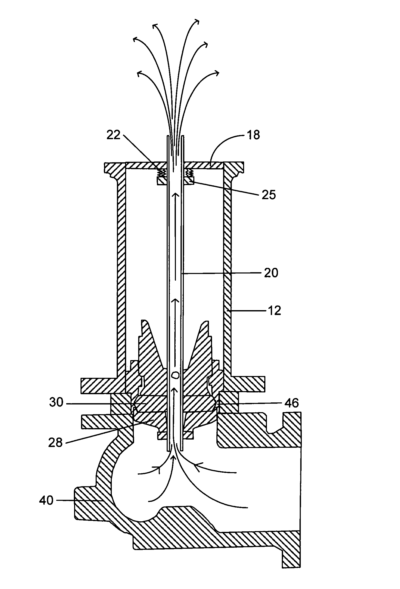
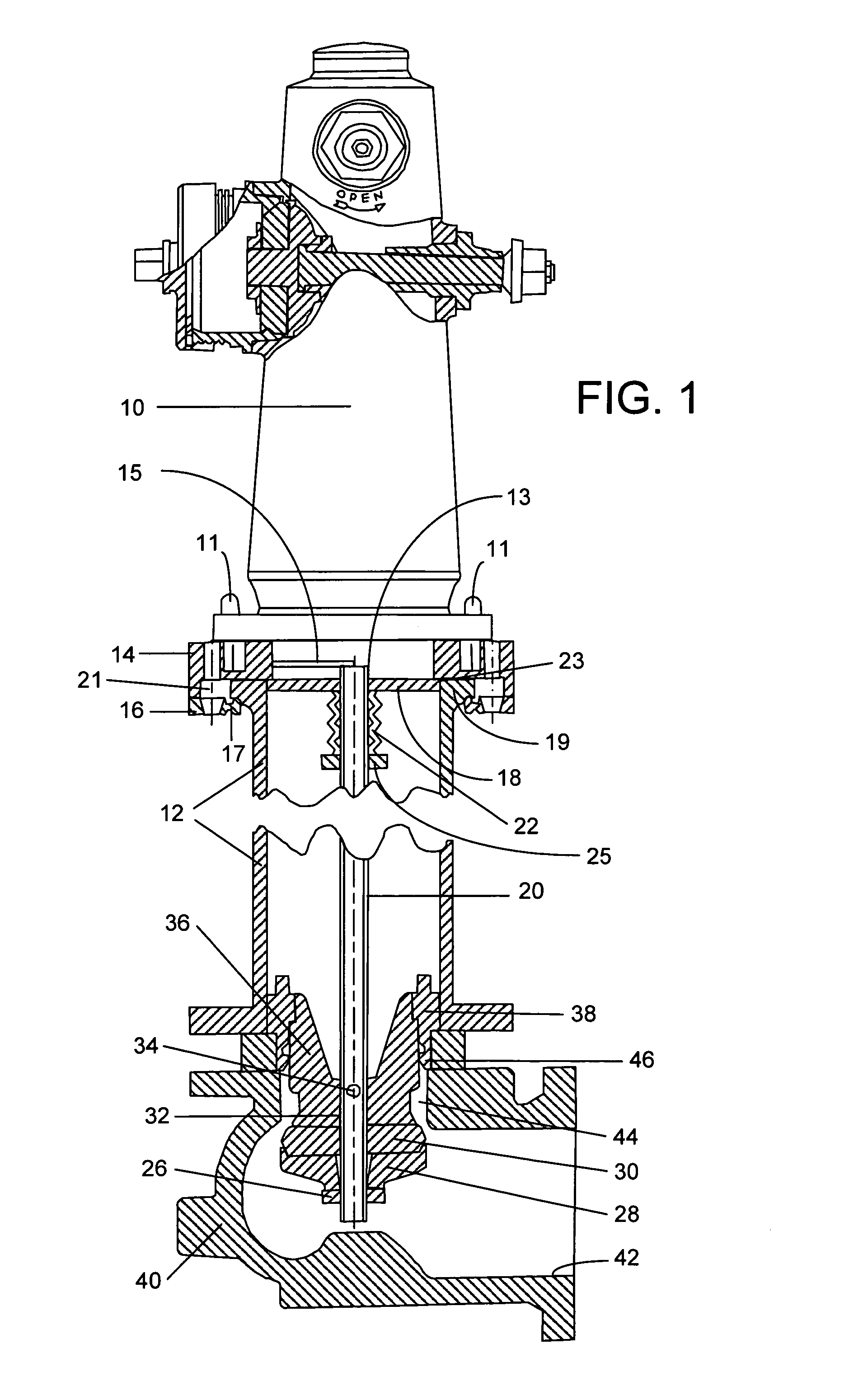
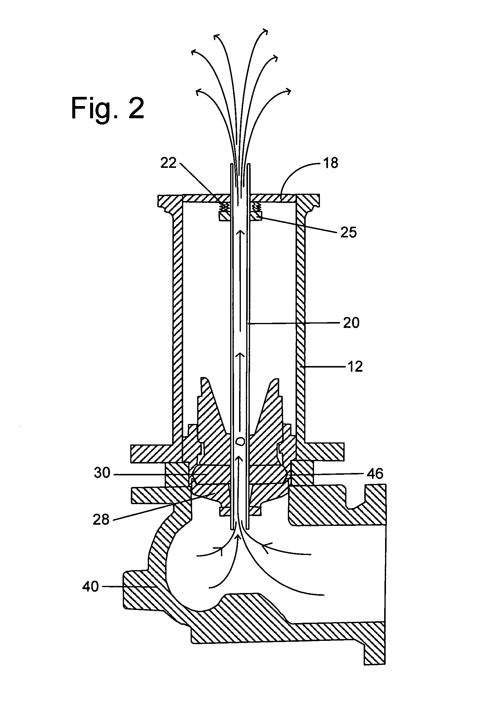
[0016]Referring to the figures, wherein like numerals represent like parts, there is shown in FIG. 1, a standard wet barrel hydrant 10 which is secured, for example, by threaded bolts 11 to a plate 14 which is mounted on the upper end of an underground barrel 12. Typically, the plate 14 is attached to a break off bracket 16 which includes an inner, annular flange 17 engaging in a grove provided in an radially extending flange 19 formed on the upper end of the underground barrel 12 as shown. With this arrangement, in the event of a collision or other force imposed on the upper barrel or hydrant 10, the flange 17 will yield to allow the plate 14 to be released from the upper end of the underground barrel 12.

[0017]Typically, the break off bracket 16 will be secured to the plate 14 by threaded bolts inserted through the threaded apertures 21. The plate 14 has an opening with an inside diameter slightly smaller in size than the diameter of the upper end of the underground barrel 12. With...


PUM


Abstract

The present invention provides a fluid flow prevention apparatus for a wet barrel fire hydrant which is simple and inexpensive to install and effectively cuts off water flow while reducing water hammer. The fluid flow apparatus includes an in-line valve member for closing a flow passageway connected to the hydrant that is operably movable from an open to closed position upon damage to the hydrant. An adjustable damping member controls the rate of closing of the valve member to reduce the effects of water hammer.

Description

[0001]This application claims priority from Provisional Patent Application Ser. No. 60 / 435,433 filed Dec. 20, 2002, entitled “Wet Barrel Fire Hydrant Flow Preventer.”BACKGROUND OF THE INVENTION[0002]1. Field of the Invention[0003]The present invention relates generally to a flow prevention apparatus for damaged fire hydrants, and more particularly, to an adjustable flow prevention apparatus for a wet barrel fire hydrant where damage to the water system elements is avoided while shut off of water flow from a damaged hydrant is simultaneously achieved.[0004]2. Description of the Related Art[0005]There are two basic types of fire hydrants manufactured today. These two types are commonly referred to in the trade as the “wet” barrel or “California” fire hydrant and the dry barrel fire hydrant. As the name implies, wet barrel fire hydrants are always supplied with water under pressure from a municipal, or other supply, water system. As such, it is the practice to install this type of fire...

Claims


Application Information

Patent Timeline
Patent Type & Authority Patents(United States)
IPC IPC(8): F16K17/14E03B9/02
CPCE03B9/02E03B9/04F16K47/023Y10T137/1789Y10T137/5327
Inventor FLEURY, JR., LEO W.MCCREARY, JOHN C.
Owner MUELLER INT LLC
Why Eureka
Try Eureka