Ultrasonic blade design for scoring double angle groove and products therefrom

a technology of ultrasonic blades and grooves, which is applied in the direction of pedestrian/occupant safety arrangements, vehicle components, other domestic objects, etc., can solve the problems of affecting the quality of work, the damage of the seam remains, and the work area is quite unpleasant, so as to prevent the side of the groove from slipping back together, prevent the reading of the front side of the skin, and score at a reasonable high rate of speed

Inactive Publication Date: 2006-10-31
COLLINS & AIKMAN PROD CO +1
View PDF36 Cites 8 Cited by
  • Summary
  • Abstract
  • Description
  • Claims
  • Application Information

AI Technical Summary

Benefits of technology

[0017]It is therefore an object of the present invention to provide a knife-blade having a double angle design which allows for the removal of sufficient material from the tear seam to prevent healing of the sides of the groove back together.
[0018]It is a further object of the present invention to provide a double angle knife-blade which provides an invisible tear seam by removing a portion of the skin material at an angle that prevents healing while leaving sufficient material remaining at the base of the groove or tear seam such that readout on the front side of the skin is prevented.
[0019]It is a further object of the present invention to provide a knife blade design which can be used on both freshly molded as well as aged shells and allow scoring at a reasonably high rate of speed.

Problems solved by technology

Additionally, some higher powered laser weakening systems may cause degradation of the skin surface where it has been thinned or weakened, resulting in a tear seam that remains tacky.
A further issue with these systems is the smoke produced, making the work area quite unpleasant.

Method used


Image

  • Ultrasonic blade design for scoring double angle groove and products therefrom
  • Ultrasonic blade design for scoring double angle groove and products therefrom
  • Ultrasonic blade design for scoring double angle groove and products therefrom

Examples


Embodiment Construction

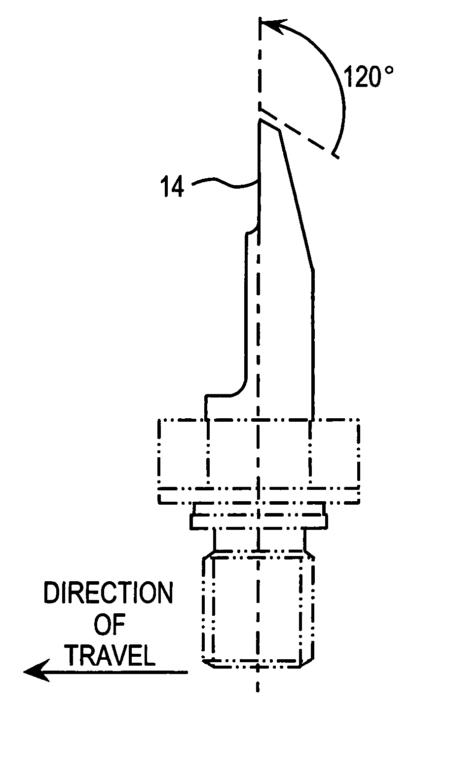
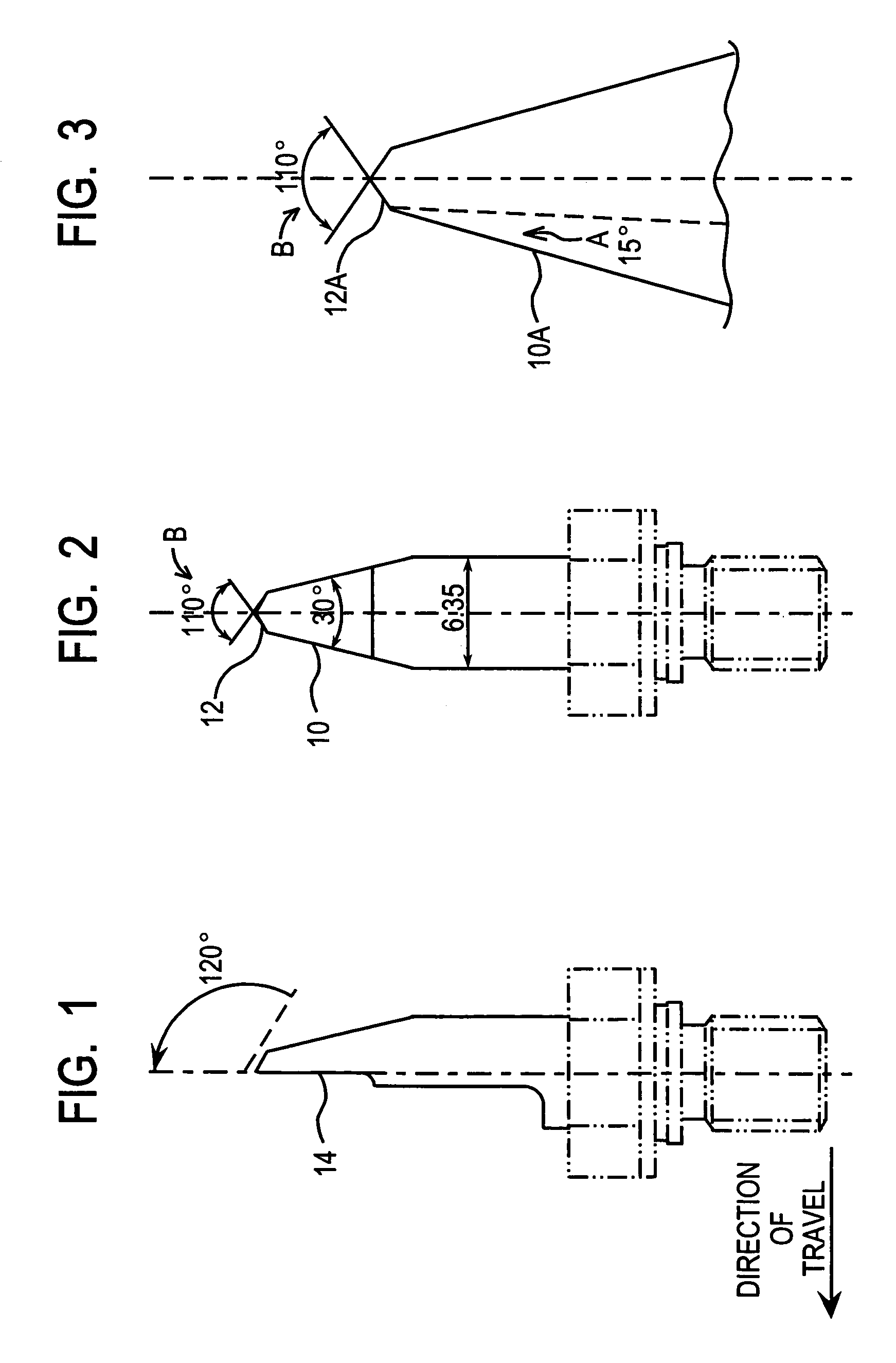
[0025]FIG. 1 illustrates a side view of the preferred ultrasonic blade that can be used in accordance with the present invention. However, it should be appreciated that in broad context, any blade that operates to provide the V-shaped groove 32 described herein is contemplated.

[0026]With attention directed to FIG. 2, as illustrated therein the blade contains a double angle V-shaped configuration. Shown at 10 is the first angle cutting surface A which angle is less than the angle of cutting surface B which is shown generally at 12. In the context of the present invention, angle A is preferably between 5–30 degrees and angle B is between 75–150 degrees. In addition it should be understood that the present invention contemplates all values therebetween in one (1) degree increments. More preferred ranges therefore include angle A of 10–20 degrees and angle B of 90–130 degrees. In a most preferred embodiment, angle A is about 15 degrees and angle B is about 110 degrees. Attention is dire...


PUM

PropertyMeasurementUnit
angleaaaaaaaaaa
angleaaaaaaaaaa
angleaaaaaaaaaa

Abstract

The present invention relates to the formation of a double angle V-groove in the backside of plastic shells to provide a preweakened section for a vehicle application. The double angle V-groove may be located at the airbag deployment opening of a vehicle.

Description

CROSS-REFERENCE TO RELATED APPLICATIONS[0001]This application claims priority to U.S. Provisional Application Ser. No. 60 / 411,458, filed Sep. 17, 2002, and is herein incorporated by reference.FIELD OF THE INVENTION[0002]The present invention relates to a method for scoring double-angle weakening grooves in skin material and products produced therefrom. The invention has particular utility in the field of automotive applications, specifically, the backside of skin sections covering airbag deployment systemsBACKGROUND OF THE INVENTION[0003]A common type of interior trim panel 2 (FIG. 4) or cover 20 used to cover and hide the air bag 40 (FIG. 5) in a motor vehicle may comprise a thin elastic plastic outer skin 22 having a non-glaring grained outer surface, a rigid retainer or substrate 26 and an intermediate layer of soft plastic foam 24 between the skin and substrate. In some cases the foam is omitted.[0004]It is common practice to use vinyl, typically polyvinyl chloride (PVC), to for...

Claims


Application Information

Patent Timeline
Patent Type & Authority Patents(United States)
IPC IPC(8): B60R21/205B29C59/00B60RB60R21/16B60R21/2165
CPCB29C59/007B60R21/2165B29L2031/3008
Inventor LELAND, RICHARD L.FUSSELL, GARY
Owner COLLINS & AIKMAN PROD CO
Why Eureka
Try Eureka