Rotor blade for a flow machine, and an associated pulling-off tool

a technology of rotor blade and flow machine, which is applied in the direction of blade accessories, machines/engines, waterborne vessels, etc., can solve the problems of small space available on the rotor blade for incorporating a threaded hole, and the threaded hole such as this is susceptible to dirt accumulation, so as to facilitate the introduction of pulling off forces and large pulling off forces

Inactive Publication Date: 2006-10-31
ANSALDO ENERGIA IP UK LTD
View PDF6 Cites 7 Cited by
  • Summary
  • Abstract
  • Description
  • Claims
  • Application Information

AI Technical Summary

Benefits of technology

[0007]The invention includes the general aspect of equipping each of the individual rotor blades with at least one pulling-off contour at the foot, which allows the necessary axial pulling-off forces to be introduced into the respective rotor blade via a pulling-off element which is complementary to this pulling-off contour. Furthermore, a pulling-off tool which is supported on the rotor while the respective rotor blade is being pulled off is proposed for driving the pulling-off element. A force introduction point is thus provided or is integrally formed with the aid of the pulling-off contour on the rotor blade, thus making it considerably easier to introduce the necessary pulling-off forces into the rotor blade. Furthermore, the position of the pulling-off contour on the rotor blade can be predetermined such that the risk of the rotor blade being tilted while being pulled off is reduced.
[0009]According to one preferred embodiment, the pulling-off contour has a web, which extends transversely with respect to the axial direction and transversely with respect to the radial direction, and forms an undercut. The pulling-off element can then engage in the undercut in order to pull the rotor blade off the rotor, and can introduce the axial pulling-off force via the web into the rotor blade. Sufficient physical space for a web such as this is available at the foot of the rotor blade. Furthermore, a web such as this can be cleaned relatively well, if arranged appropriately. In addition, a web such as this can be designed without any problems such that sufficiently large pulling-off forces can be transmitted.
[0010]The pulling-off tool has a drive device which axially drives the pulling-off element in the pulling-off direction while the rotor blade is being pulled off the rotor. In one preferred embodiment, this drive device may have a slide, which supports the pulling-off element and can be moved by means of a drive axially along a bracket which has a supporting contour, via which the pulling-off tool is supported axially on the rotor while the rotor blade is being pulled off. The support for the reaction forces on the rotor results in an intrinsically closed power flow, which requires no external support for the reaction forces and thus makes it considerably easier to introduce the pulling-off forces.

Problems solved by technology

However, relatively little space is available on the rotor blade for incorporating a threaded hole such as this.
Furthermore, a threaded hole such as this is susceptible to dirt accumulation.

Method used


Image

  • Rotor blade for a flow machine, and an associated pulling-off tool
  • Rotor blade for a flow machine, and an associated pulling-off tool
  • Rotor blade for a flow machine, and an associated pulling-off tool

Examples


Embodiment Construction

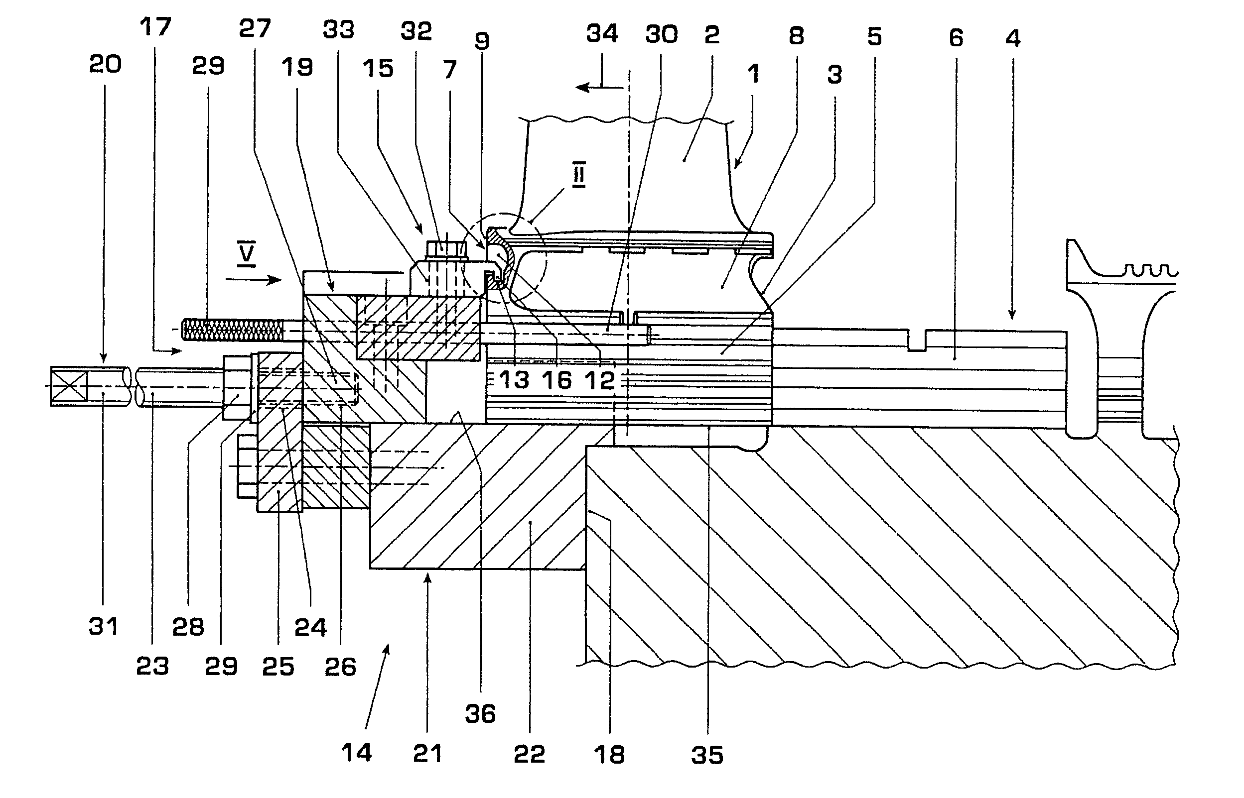
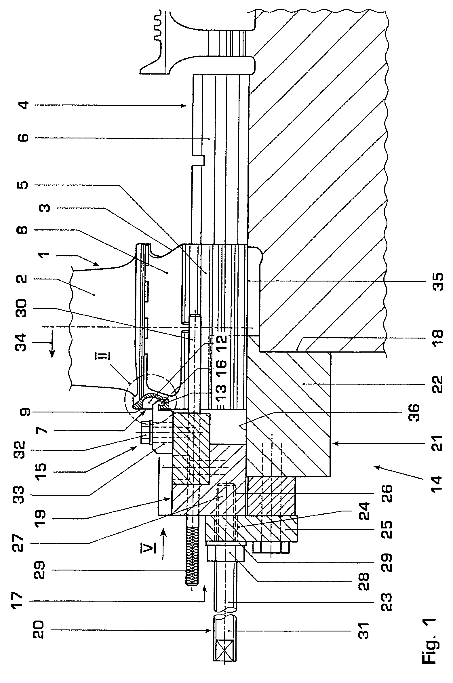
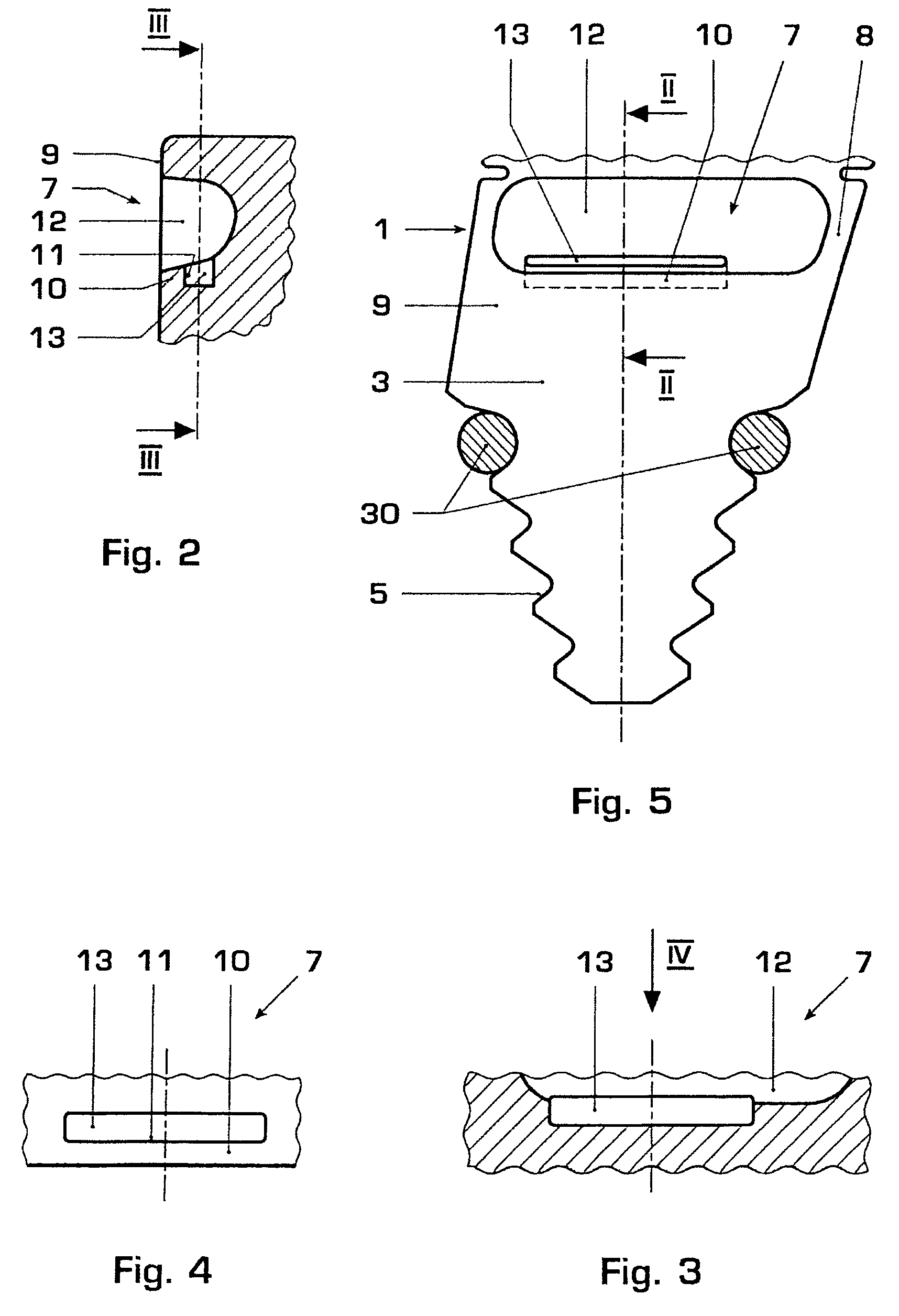
[0019]As is shown in FIG. 1, a rotor blade 1 according to the invention normally has an aerodynamically shaped blade 2, which is used for flow guidance, as well as a foot 3, by means of which the rotor blade 1 can be attached to a rotor 4 of a flow machine, for example a turbine or a compressor. As is shown in FIGS. 1 and 5, an anchoring section 5 is formed on a side of the foot 3 facing away from the blade 2 for these attachment purposes, which anchoring section 5 in each case has a type of tooth system on sides which face away from one another in the circumferential direction of the rotor 4, with these tooth systems converging in the direction of a rotation axis of the rotor 4. A tooth system contour such as this may also be referred to as a “fir-tree tooth system”.

[0020]As is shown in FIG. 1, the rotor 4 has an axial anchoring groove 6 for each rotor blade 1, that is to say an anchoring groove which runs parallel to the rotation axis of the rotor 4, which is shaped to be compleme...


PUM

PropertyMeasurementUnit
axial pulling-off forceaaaaaaaaaa
forceaaaaaaaaaa
areaaaaaaaaaaa

Abstract

A rotor blade (1) for a flow machine includes an aerodynamic blade (2) and a foot (3). The foot (3) has an anchoring section (5) on a side facing away from the blade (2). A rotor (4) of the flow machine has an axial anchoring groove (6) which is complementary to the anchoring section (5). The anchoring section (5) can be inserted axially into the anchoring groove (6) in order to radially attach the rotor blade (1) to the rotor (4). At least one pulling-off contour (7) is formed on the foot (3), via which an axial pulling-off force can be introduced into the rotor blade (1), which is attached to the rotor (4) with the aid of a pulling-off tool (15) which is complementary to this pulling-off contour (7).

Description

[0001]This application claims priority to German application number 103 44 098.4, filed 24 Sep. 2003, the entirety of which is incorporated by reference herein.BACKGROUND OF THE INVENTION[0002]1. Field of the Invention[0003]The present invention relates firstly to a rotor blade for a flow machine, and secondly to a pulling-off tool for pulling a rotor blade such as this off a rotor of the flow machine.[0004]2. Brief Description of the Related Art[0005]Rotor blades normally have an aerodynamic blade as well as a foot, by means of which the rotor blade can be anchored in a rotor of the flow machine. For this purpose, the foot may have an anchoring section on a side facing away from the blade, which anchoring section can be inserted axially into an anchoring groove which is complementary to it and is axial with respect to the rotation axis of the rotor. The shapes of the anchoring section and of the anchoring groove are in this case matched to one another such that an interlock is form...

Claims


Application Information

Patent Timeline
Patent Type & Authority Patents(United States)
IPC IPC(8): F01D5/30B25B27/02F01D5/00
CPCB23P6/002B23P19/025B25B27/023F01D5/005F01D5/323F01D25/285F05D2230/70
Inventor ANNER, EMILSLOUTSKI, EDOUARDTCHEKANOV, ALEXANDRETSCHUOR, REMIGI
Owner ANSALDO ENERGIA IP UK LTD
Why Eureka
Try Eureka