Air filter retaining system

a filter and retaining system technology, applied in the field of filter retaining systems, can solve the problems of air leakage downstream in the gaps between individual frame members and also between the filter and the frame, loss, and spring clips cannot hold the pre-filter in place, so as to prevent air from bypassing the filter, improve sealing, and add rigidity to the retaining system

Active Publication Date: 2006-10-31
TOTAL FILTRATION MFG
View PDF12 Cites 41 Cited by
  • Summary
  • Abstract
  • Description
  • Claims
  • Application Information

AI Technical Summary

Benefits of technology

[0009]A filter retaining system formed from multiple filter retaining frames is disclosed. Each of the frames is formed from either a female type extrusion or a combination of male and female type extrusions. Specifically, each frame has either a tongue or a groove which is engageable into a corresponding groove or tongue of an adjacent frame. The tongue and groove engagement provides added rigidity to the retaining system, as well as preventing air from bypassing the filters retained within each frame.
[0010]Additionally, each frame includes snaplocks which retain the filter against the frame. Each snaplock is attached to the frame and is used to retain a primary filter as well as a pre-filter (if necessary). The extrusions further include a knife edge that forms a seal against the filter. The snaplocks compress the filter against the knife edge in order to seal the filter to the frame. Additionally, a neoprene gasket may be placed between the filter and the knife edge in order to provide a better seal.
[0011]Additionally, in order to provide a good seal between adjacent frames, each extrusion is formed with a sealing member that is used in conjunction with a gasket to prevent air from bypassing the filters. The sealing member is formed around the outside of each frame. The gasket is positioned between adjacent sealing members when the frames are attached together. Multiple gaskets and sealing members may be provided in order to further decrease the chance of air bypassing the filters.
[0012]Each of the extrusions is also formed with grooves that are disposed on the outside of each frame. The grooves provide a channel for an L bracket to attach the extrusions together into a rectangular shape to form the frame. The extrusions are also formed with extrusion arms that define a stiffener channel when the frames are attached together. A vertical stiffener, such as an I-beam, can be inserted within the channel in order to provide rigidity to the system.

Problems solved by technology

Numerous problems develop with the type of filter retaining assembly described above.
Specifically, air can leak downstream in the gaps between individual frame members and also between the filter and the frame.
The spring clips that are used to fasten the filters to the frame can become unfastened to the frame when the filter is not in place and can become lost.
Furthermore, the spring clips cannot hold the pre-filter in place when air is not flowing.
Another problem occurs when multiple frames are stacked together to form an array of filters.
The array of frames will flex due to their lack of rigidity.
The flexure of the frames will cause gaps between the frames and the filters, and adjacent frames thereby leaking contaminants into the airstream.

Method used


Image

  • Air filter retaining system
  • Air filter retaining system
  • Air filter retaining system

Examples


Embodiment Construction

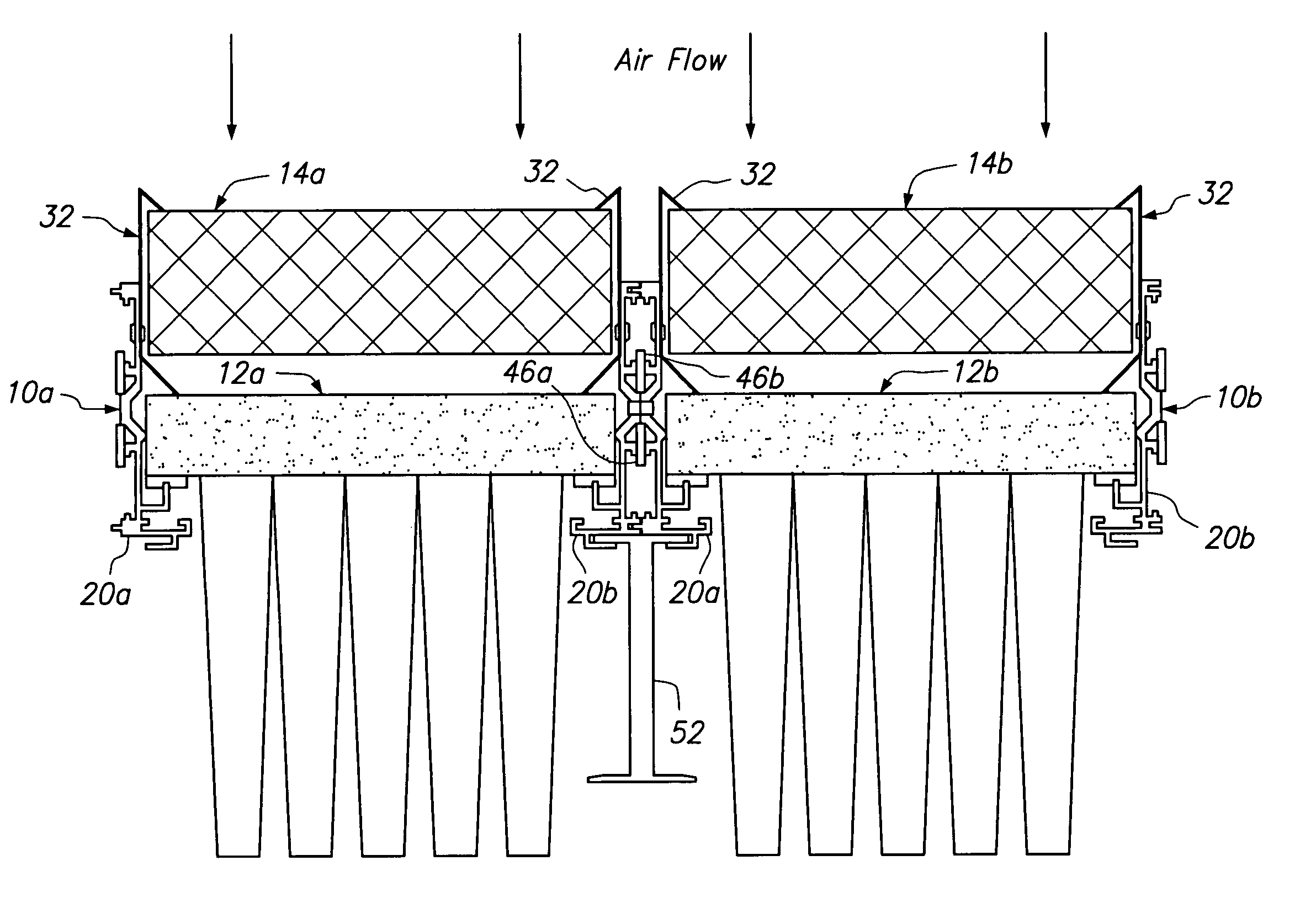
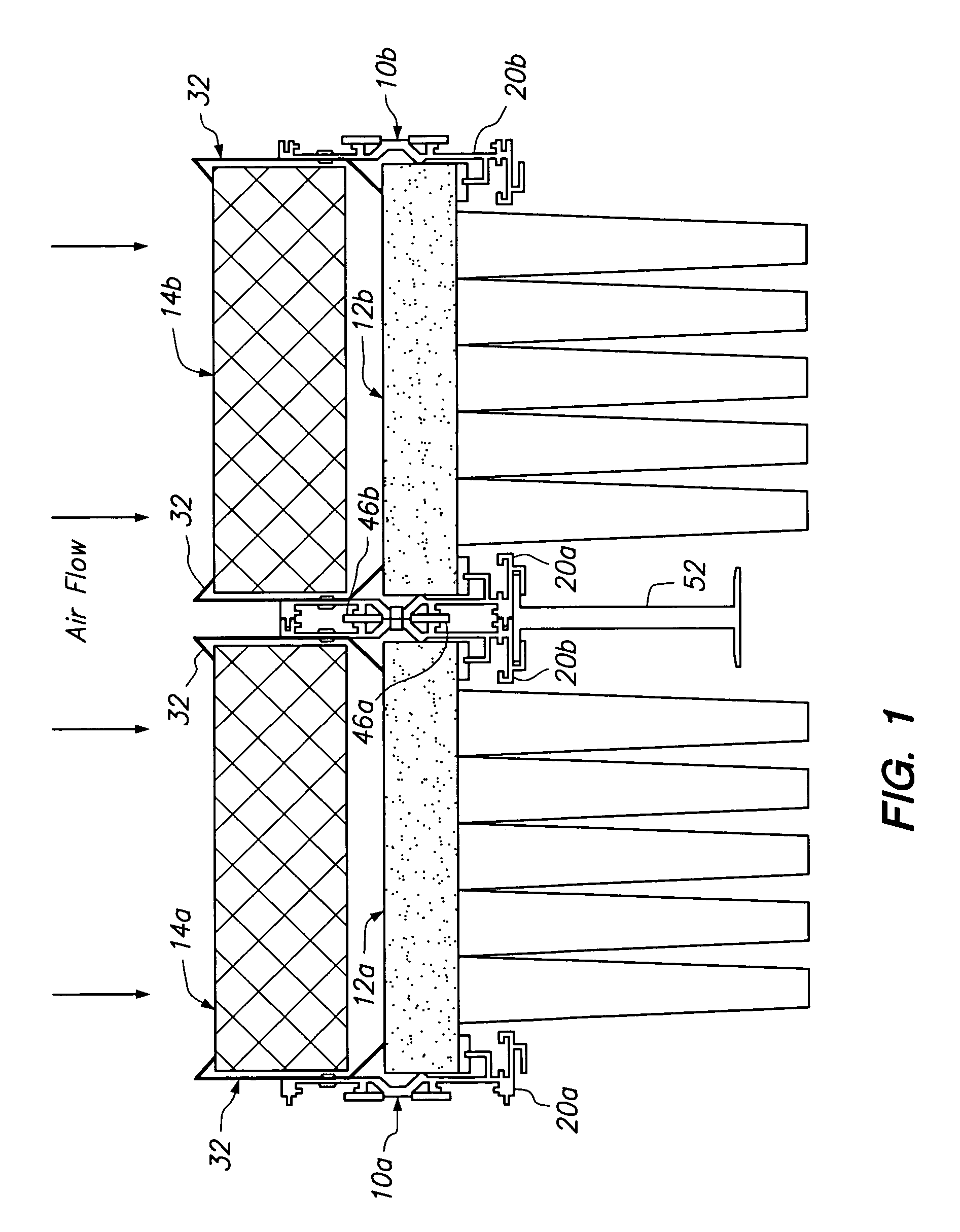
[0019]Referring now to the drawings wherein the showings are for purposes of illustrating a preferred embodiment of the present invention only, and not for purposes of limiting the same, FIG. 1 is a cross-sectional view of two filter retainer frames 10a and 10b. Each filter retaining frame 10 is sized to accept a respective primary filter 12a, 12b. Pre-filters 14a, 14b can be positioned upstream of the primary filters 12, as will be further explained below.

[0020]As seen in FIG. 4, the filter retainer frames 10a–10i are arranged to form a filter retaining system 16. Each frame 10 is used to hold a filter 12 with an optional pre-filter 14. As will be further explained below, each of the frames 10 are designed to be interlocking with an adjacent frame in order to provide precise alignment of the filters 12 in frames 10, along with providing an airtight seal between adjacent frames.

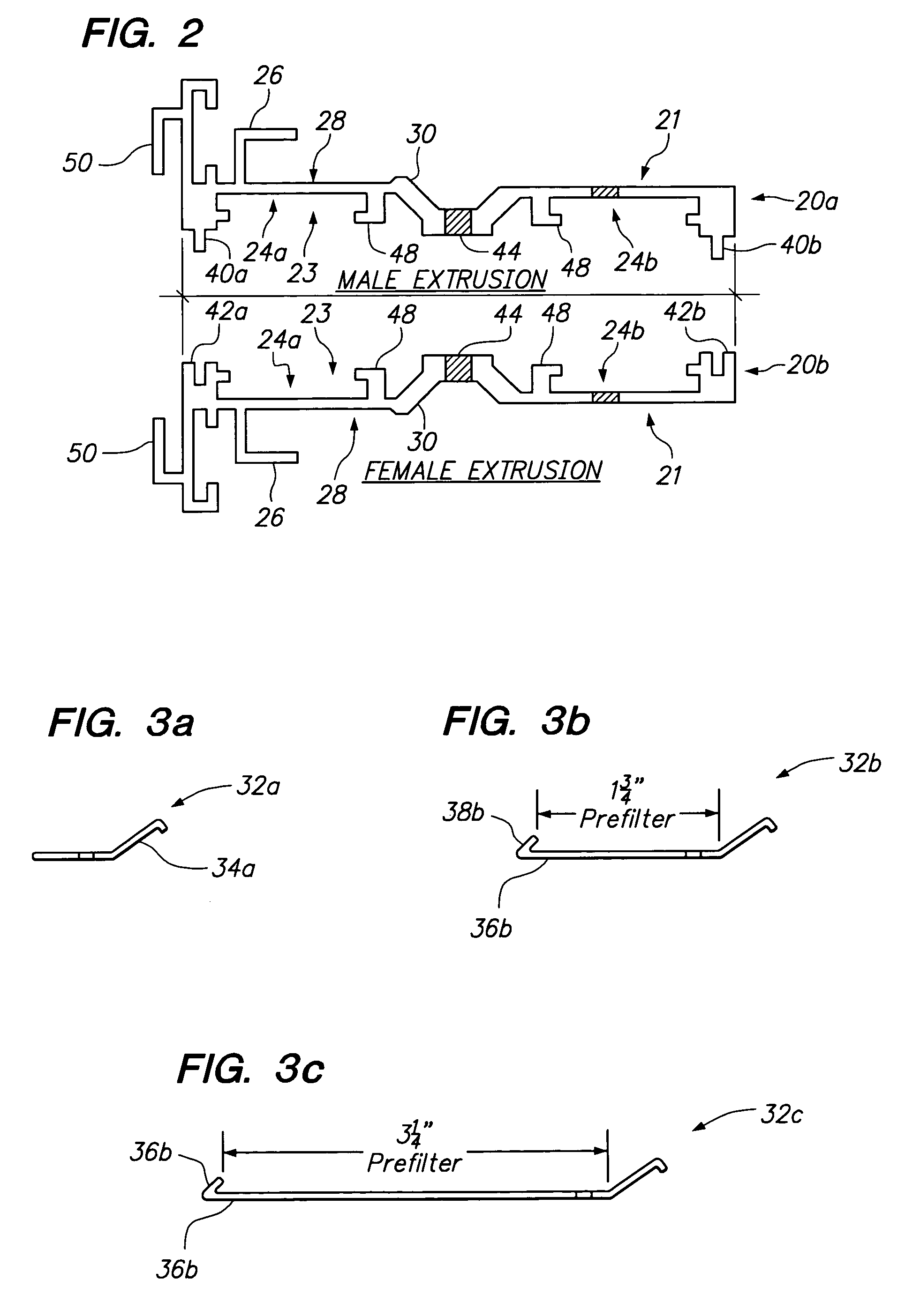
[0021]Each frame 10 is formed by assembling four frame extrusion 20 into a generally rectangular pattern. ...


PUM

PropertyMeasurementUnit
sizesaaaaaaaaaa
lengthaaaaaaaaaa
lengthsaaaaaaaaaa

Abstract

A filter retaining system formed from multiple filter retaining frames is disclosed. Each of the frames is formed from either a female type extrusion or a combination of male and female type extrusions. Specifically, each frame has either a tongue or a groove which is engageable into a corresponding groove or tongue of an adjacent frame. The tongue and groove engagement provides added rigidity to the retaining system, as well as preventing air from bypassing the filters retained within each frame.

Description

[0001]This application claims the benefit of U.S. Provisional Application No. 60 / 482,123, filed Jun. 25, 2003, the contents of which are incorporated herein by reference.FIELD OF THE INVENTION [0002]The present invention relates generally to filter retention systems and more particularly to a modular framework for retaining air filters that virtually eliminates unfiltered air passing downstream.BACKGROUND OF THE INVENTION [0003]The requirements for clean air have forced engineers and building owners to improve the quality of air filtration devices used in office buildings and sophisticated “zero” tolerance clean rooms. In many buildings, air filtration devices comprise a series of filters placed upstream of the HVAC system. The filters are used to remove the contaminants in the air flowing through the HVAC system.[0004]Typically, the filters are placed within a filter bank assembly having frames for holding each respective filter. The frames are fastened together to form an array of...

Claims


Application Information

Patent Timeline
Patent Type & Authority Patents(United States)
IPC IPC(8): B01D46/00B01D46/12
CPCB01D46/0013B01D46/002B01D46/4236Y10S55/31B01D46/58
Inventor HARDEN, CHARLES MICHAEL
Owner TOTAL FILTRATION MFG
Why Eureka
Try Eureka