
Separate-type musical performance system for synchronously producing sound and visual images and audio-visual station incorporated therein

a musical performance system and synchronization technology, applied in the field of remote control technology of audio visual reproducer, can solve the problems of synchronization being less accurate, synchronization prone to breakage, and inability to ensure that audio data codes and visual data codes timely reach the videophone b

Inactive Publication Date: 2006-10-31
YAMAHA CORP
View PDF13 Cites 97 Cited by
  • Summary
  • Abstract
  • Description
  • Claims
  • Application Information

AI Technical Summary

Benefits of technology

This approach ensures synchronized production of music sound and visual images, maintaining synchronization despite network delays and varying data processing speeds, providing accurate and reliable remote musical performances.

Problems solved by technology

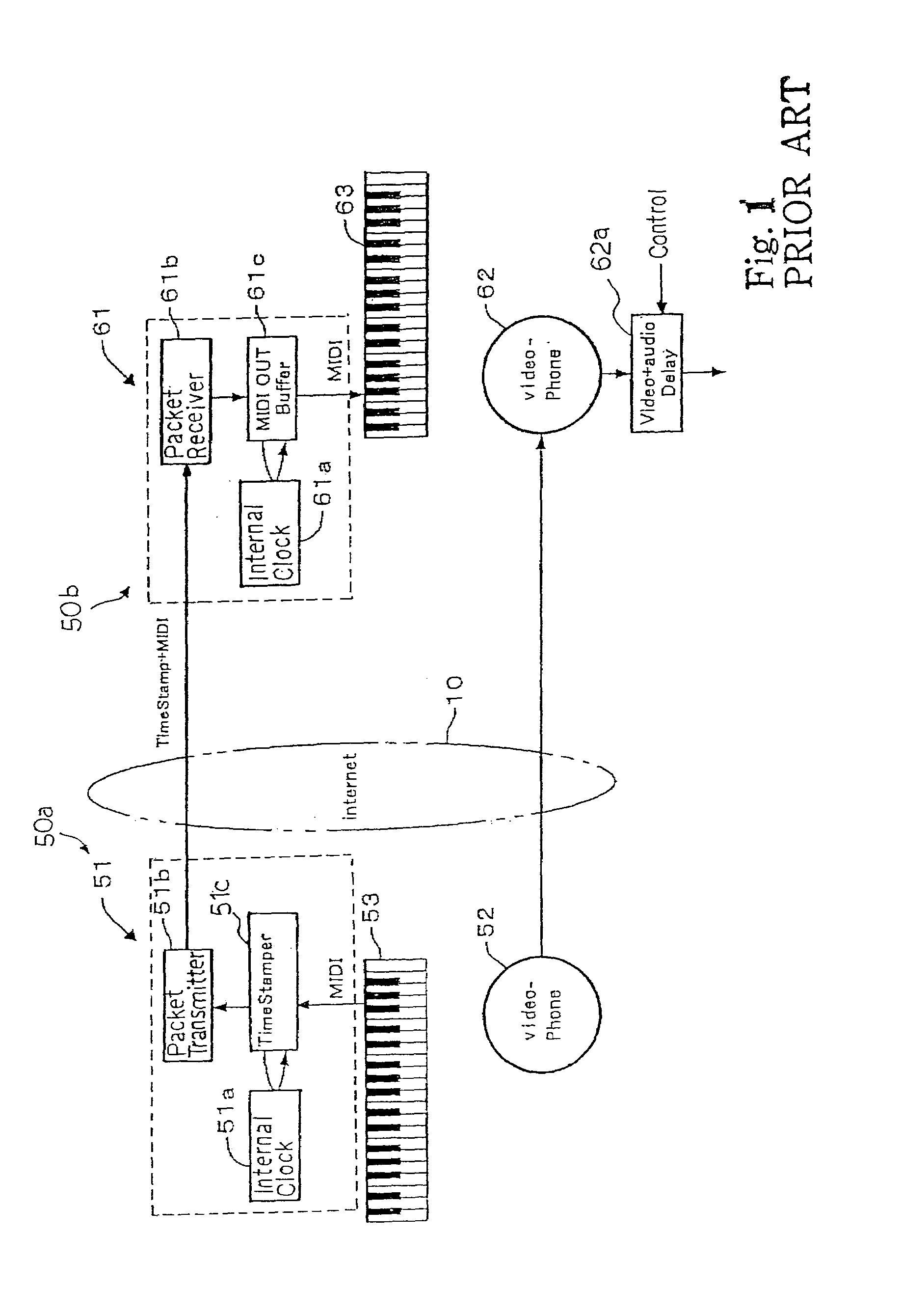
Nevertheless, there is not any guarantee that the audio data codes and visual data codes timely reach the videophone 62.
Even though the human operator manually synchronizes the visual images and voice with the electronic tones, the synchronism is liable to be broken due to, for example, the traffic of the communication network or the difference in data processing speed between the packet transmitter module 51b and the videophone 52.
Moreover, the synchronization is less accurate, because the accuracy is dependent on the sense of sight and sense of hearing.
Thus, the problem inherent in the prior art separate-type music performance system is the poor synchronization between the electronic tones and the visual images / voice.
It is difficult to apply the synchronizing techniques to the separate-type musical performance system, because any real time network communication is not taken into account in the synchronizing techniques.

Method used


Image

  • Separate-type musical performance system for synchronously producing sound and visual images and audio-visual station incorporated therein
  • Separate-type musical performance system for synchronously producing sound and visual images and audio-visual station incorporated therein
  • Separate-type musical performance system for synchronously producing sound and visual images and audio-visual station incorporated therein

Examples


Embodiment Construction

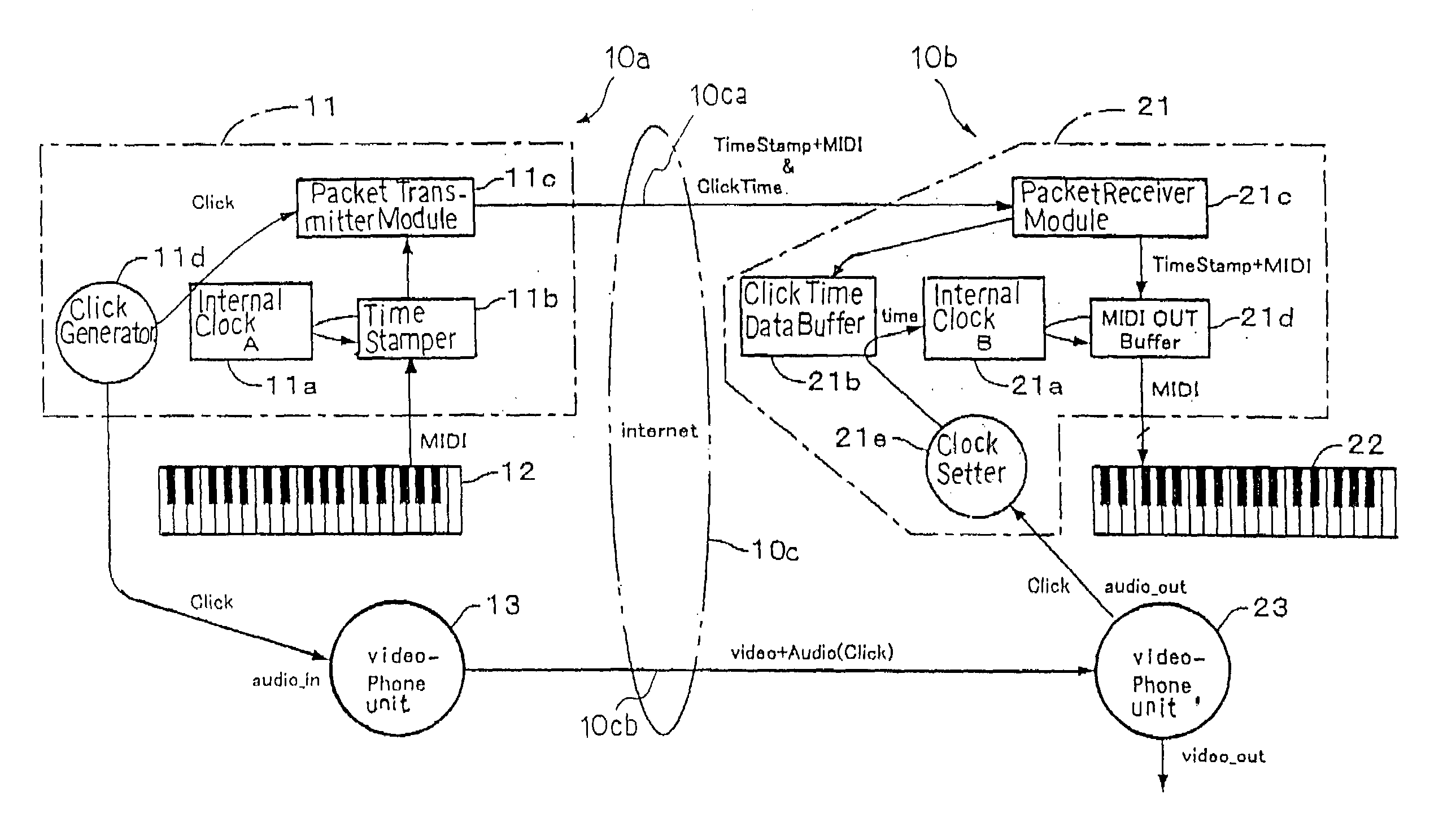
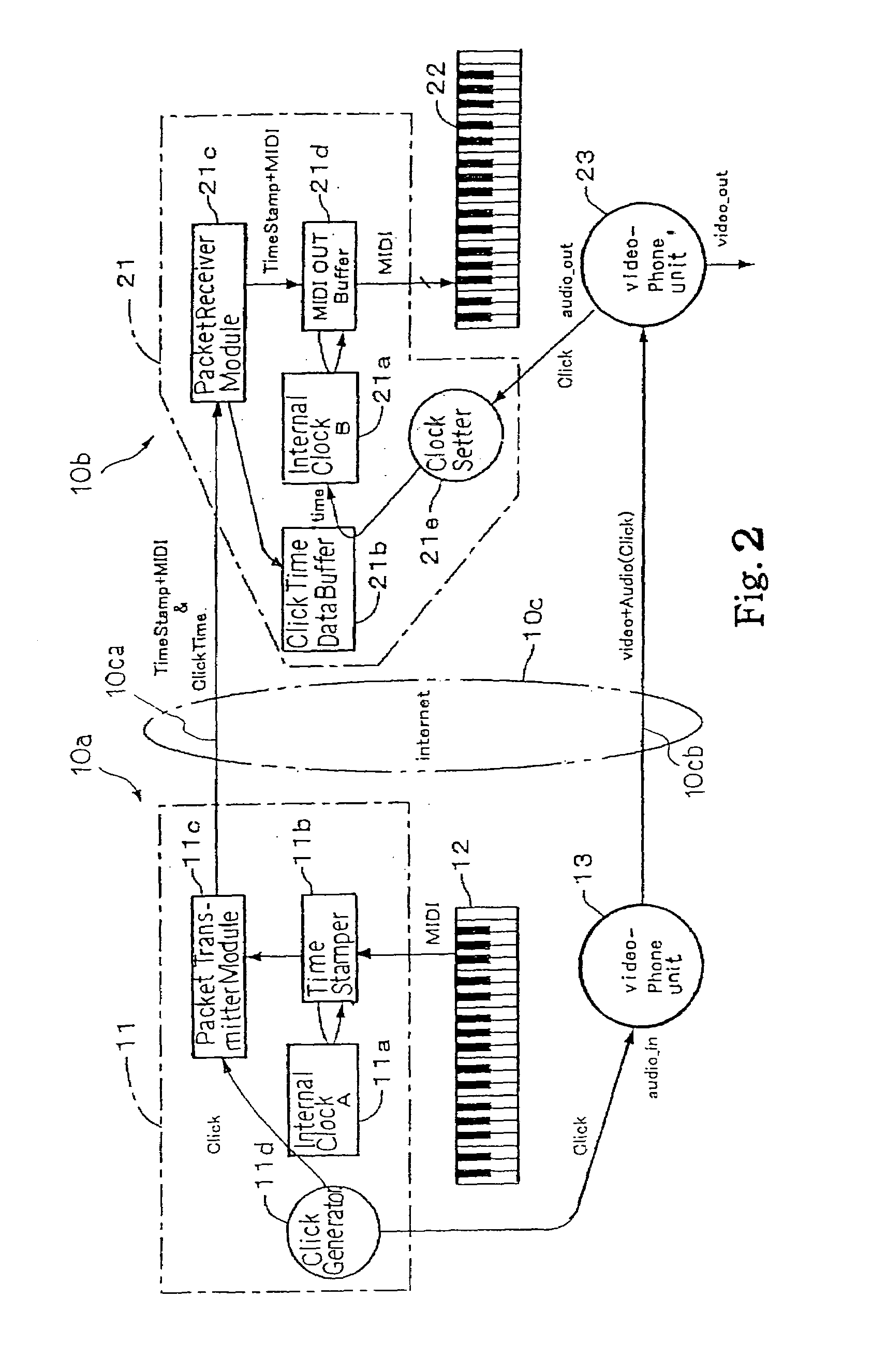
[0031]In the following description, term “MIDI music data” means messages defined in the MIDI protocols, and term “MIDI music data codes” is representative of the MIDI music data, which are coded in the formats defined in the MIDI protocols. Term “audio-visual data” is representative of visual images and / or voice. Term “analog audio-visual signal” is representative of an analog signal, which carries the audio-visual data, and term “audio-visual signal data codes” is representative of a digital signal, which carries the audiovisual data.

[0032]Term “click data” is information that a click occurs, and term “click time” is indicative of a time when a click occurs. Term “click time data” is information indicative of the click time. Term “click time data code” is a binary code representative of the clock time data. Term “click signal” is a predetermined pulse train representative of each click.

[0033]Term “stamp time” is indicative of a time when a MIDI music data code or codes are stamped...


PUM


Abstract

A separate-type music performance system has a master audio-visual station and a slave audio-visual station remote from the mater audio-visual station and connected through two communication channel independently of each other; MIDI music data codes and click time data codes are transmitted through one of the communication channels to the slave audio-visual station, and audio-visual data codes and a click signal are transmitted through the other communication channel; when the click signal and click time data code arrive the slave audio-visual station, the clock setter 21e sets an internal clock with the click time data code paired with the click signal, and the MIDI music data code are transferred to an automatic player piano in comparison with the time data and the internal clock, whereby the tones are produced synchronously with the visual images.

Description

FIELD OF THE INVENTION[0001]This invention relates to a remote controlling technology for an audio visual reproducer and, more particularly, to a separate-type musical performance system and an audio-visual station incorporated in the musical performance system.DESCRIPTION OF THE RELATED ART[0002]In a case where a musician or musicians are to be remote from audience, a separate-type musical performance system is required for the concert. A tutor may give music lessons to students remote from him or her. In this situation, the separate-type musical performance system is also required for the remote lessons. The separate-type musical performance system includes a master audio-visual station and a slave audio-visual station, and the master audiovisual station communicates with the slave audio-visual station through a communication network. While the musicians are performing a piece of music on the master audio-visual station, audio data, which represent the tones produced along the pie...

Claims


Application Information

Patent Timeline
Patent Type & Authority Patents(United States)
IPC IPC(8): G10H7/00H04N5/073G10H1/00
CPCG10H1/0066G10H2240/305
Inventor UEHARA, HARUKI
Owner YAMAHA CORP
Learn More