Movable contact element and panel switch using the same

a technology of moving contact and panel switch, which is applied in the direction of moving contacts, pulse techniques, coding, etc., can solve the problems of electronic devices not providing the user with a predetermined level of operation feeling, and the slight misalignment, so as to simplify the production and integration process, excellent operation feeling, and excellent operation feeling

Inactive Publication Date: 2006-10-31
PANASONIC CORP
View PDF8 Cites 9 Cited by
  • Summary
  • Abstract
  • Description
  • Claims
  • Application Information

AI Technical Summary

Benefits of technology

[0022]The present invention has overcome these conventional problems. When a movable contact point is integrated into a movable contact element, or a movable contact element is integrated into a touch panel, even if there is a slight misalignment between manual operation buttons, it is still possible to maintain excellent operation feeling on the touch panel and also to simplify the integration process, thereby achieving a reliable movable contact element and a panel switch using it.
[0024]This structure can eliminate the detachment of the spacer piece from the base sheet, and can also control variation in production and integration processes. Furthermore, when the movable contact element is integrated into an electronic device to form a panel switch, even if there is a slight misalignment between the center of the movable contact point and the corresponding manual operation button, the manual operation button never fails to press the pressed part of the movable contact point that is formed as the small protrusion. This structure provides the user with excellent operation feeling.
[0025]Another movable contact element of the present invention includes a movable contact point having a throughhole at the center of the domed part. The top surface of the spacer piece is fixedly bonded to the bottom surface of the base sheet by the adhesive applied on the bottom surface of the base sheet, and the bottom surface of the spacer piece is placed on the outer surface of the domed part of the movable contact point. Since the movable contact point and the spacer piece are not fixed to each other, the movable contact point in operation is not affected by the spacer piece. Furthermore, the throughhole allows air to be moved in and out of the movable contact point. This prevents the operation feeling from being degraded due to air compression or the like, thereby providing the user with excellent operation feeling.
[0027]This movable contact element never causes the detachment of the pressed part of the movable contact point, so that excellent operation feeling can be maintained for a long time.
[0028]As described hereinbefore, in the present invention, the spacer piece is sandwiched between the base sheet and the domed part of the movable contact point, and the portion of the base sheet having the spacer piece thereunder is swollen upward, i.e., toward manual operation button 6 so as to form the small protrusion, which functions as the pressed part of the movable contact point. This structure can simplify the production and integration processes of the movable contact element and the touch panel. Furthermore, when integrated into an electronic device, the movable contact element and the panel switch can provide the user with excellent operation feeling for a long time.

Problems solved by technology

However, when the panel switch is integrated into various electronic devices, variation in production processes and workability causes a slight misalignment between manual operation button 6 and the center of movable contact point 1.
As a result, the electronic devices fail to provide the user with a predetermined level of operation feeling.

Method used


Image

  • Movable contact element and panel switch using the same
  • Movable contact element and panel switch using the same
  • Movable contact element and panel switch using the same

Examples


embodiment

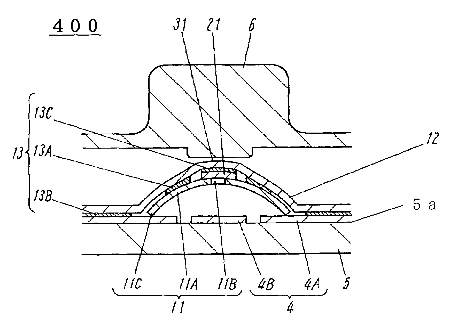
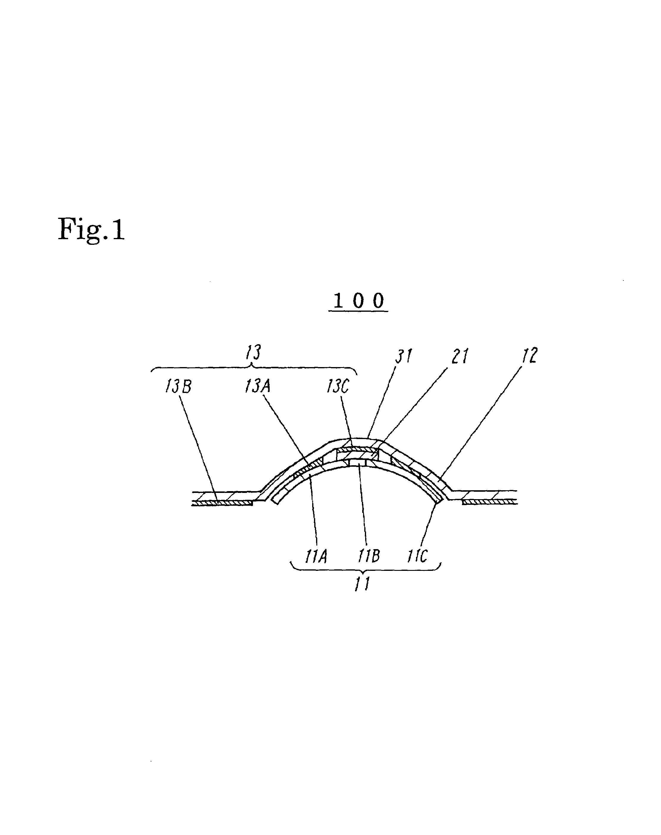
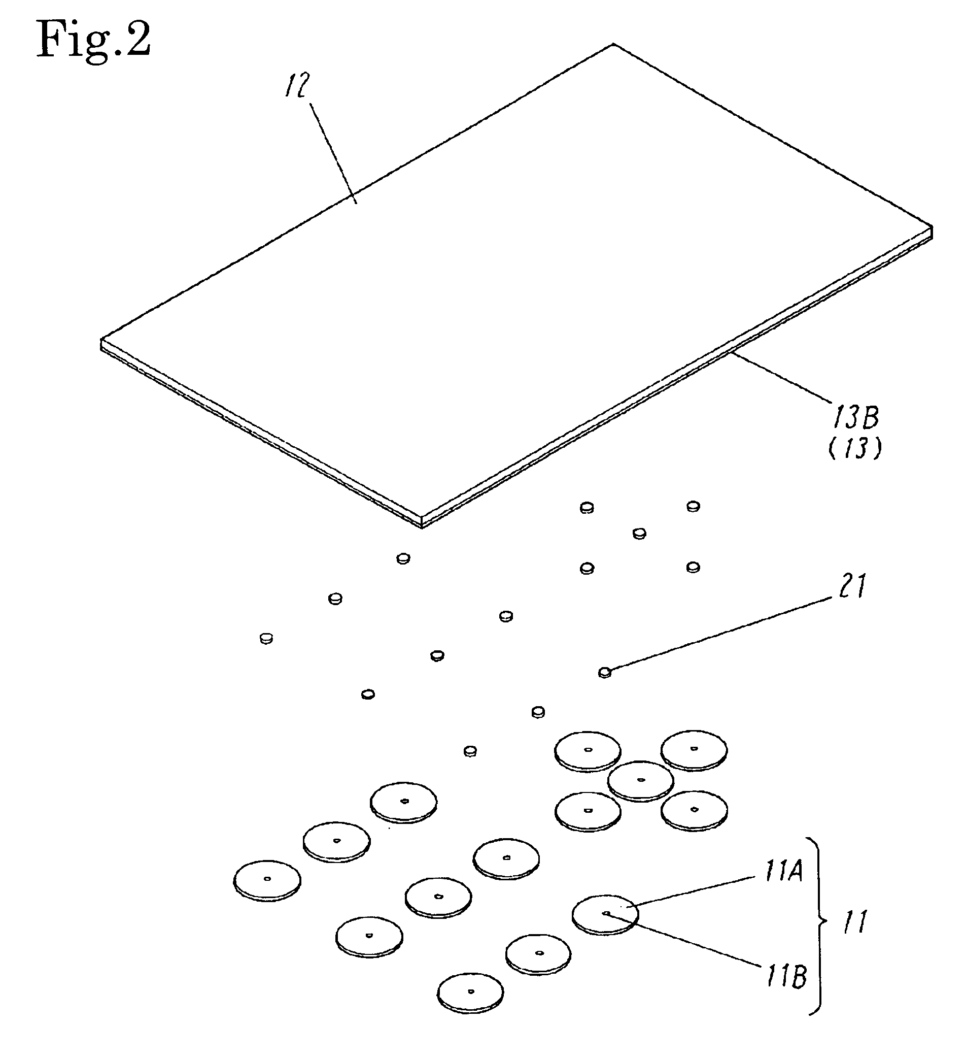
[0039]FIG. 1 is a cross sectional view of a movable contact element of the embodiment of the present invention. Movable contact element 100 shown in FIG. 1 includes movable contact point 11 made of an elastic metal thin film. Movable contact point 11 is circular when seen from above, and has a convexly domed top and an open bottom. Domed part 11A of movable contact point 11 has circular throughhole 11B at its center, and circumferential bottom edge 11C at its end.

[0040]Base sheet 12 is made of an insulating film such as PET, and has adhesive 13 applied by, e.g. printing it on its bottom surface. Adhesive 13 is applied in the shapes of circular ring part 13A, peripheral part 13B and small-diameter circular part 13C. Movable contact point 11 is positioned in such a manner that the center of throughhole 11B is vertically aligned with the center of circular ring part 13A. Domed part 11A is fixedly bonded at its outer surface to base sheet 12 by circular ring part 13A of adhesive 13 appl...


PUM


Abstract

Provided are a movable contact element used in a panel switch on the operation panel of various electronic devices and a panel switch using the movable contact element, which provide excellent operation feeling and simplify the production and integration processes. Between base sheet and the center of the outer surface of domed part of movable contact point is disposed spacer piece. Base sheet has a small protrusion swollen upward on its top surface, and the small protrusion serves as pressed part. This structure can eliminate the detachment of spacer piece from base sheet, and can also both simplify and improve reliability of the production and integration processes of the movable contact element and the panel switch. Providing pressed part ensures that the center of movable contact point is fully pressed down to a predetermined level, thus providing the user with excellent operation feeling.

Description

FIELD OF THE INVENTION[0001]The present invention relates to a movable contact element used in a panel switch on the operation panel of various electronic devices, and also to a panel switch using the movable contact element.BACKGROUND OF THE INVENTION[0002]In recent years, more and more portable electronic devices such as mobile phones and PDAs (Personal Digital Assistances) are having a panel switch using a movable contact element on the operation unit. A conventional movable contact element and a panel switch using it will be described as follows with reference to drawings.[0003]FIG. 5 is a cross sectional view of the movable contact element, FIG. 6 is an exploded perspective view of the movable contact element, FIG. 7 is a view showing application of adhesive to the area of a base sheet that corresponds to a movable contact point as a component of the movable contact element, and FIG. 8 is a cross sectional view of the conventional panel switch using the movable contact element....

Claims


Application Information

Patent Timeline
Patent Type & Authority Patents(United States)
IPC IPC(8): H01H1/10
CPCH01H13/7006H01H2205/026H01H2213/00H01H2215/026H01H2217/01H01H2221/05H01H2229/028H01H2229/064
Inventor SANO, YOSHIRO
Owner PANASONIC CORP
Why Eureka
Try Eureka