Snapshot backscatter radiography (SBR) systems including system having dynamic collimation

a radiography and backscatter technology, applied in the field of radiography, can solve the problems of large exposure times for typical radiation sources, inability to use image-gathering lenses, and inability to accurately measure the radiation intensity of the target area, so as to improve the resolution and improve the measurement sensitivity

Inactive Publication Date: 2006-10-31
UNIV OF FLORIDA RES FOUNDATION INC
View PDF2 Cites 65 Cited by
  • Summary
  • Abstract
  • Description
  • Claims
  • Application Information

AI Technical Summary

Benefits of technology

[0012]A radiation source controller is also preferably provided. The radiation source controller can permit the system to produce 3 dimensional (3-D) radiation data which permits the generation of a 3-D image of the object. For example, the radiation source controller can direct the radiation source to provide multiple bursts at varying radiation energy or temporal variation of a radiation energy spectrum.
[0013]The system can also include one or more collimator grids disposed between the object region and the detector. Collimating grids can be used to improve resolution or help isolate a lateral migration component of the backscattered radiation. The invention also includes an embodiment having dynamic collimators which can further improve measurement sensitivity.

Problems solved by technology

Because of the absence of a refraction process for the penetrating radiation in backscatter radiography, image-gathering lenses cannot be used.
This generally results in either extremely inefficient sensing of the radiation, or the introduction of substantial image-obscuring structured noise, thus requiring large exposure times for typical radiation sources.
This also yields long exposure times and decoding algorithms having long calculation times, besides requiring an expensive scanning apparatus.

Method used


Image

  • Snapshot backscatter radiography (SBR) systems including system having dynamic collimation
  • Snapshot backscatter radiography (SBR) systems including system having dynamic collimation
  • Snapshot backscatter radiography (SBR) systems including system having dynamic collimation

Examples


example

[0071]The present invention is further illustrated by the following example. This example is provided for illustration only and is not to be construed as limiting the scope or content of the invention in any way.

[0072]SBR was tested in a single measurement which successfully imaged a high-contrast feature in an optimal configuration of an SBR system according to the invention using x-rays and a computed radiography (CR) screen detector with the associated image reader replacing the image-analyzing computer. The object (and “structure”) was a plastic block on the interrogated surface which included a small (1 cm×1 mm×0.1 mm thick) strip of lead. From the SBR image obtained the lead strip was clearly visible, with about 0.1 mm resolution being provided.

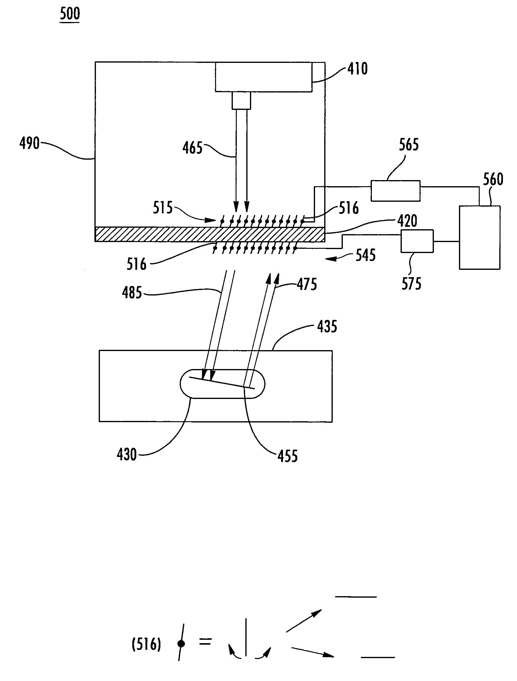
Exemplary Grid Sequencing for Snapshot Radiography using Radiography System having Dynamic Collimators

[0073]An exemplary timing sequence of events is provided for a two dynamic collimator grid snapshot radiography system, such as system...


PUM

PropertyMeasurementUnit
rotation anglesaaaaaaaaaa
thickaaaaaaaaaa

Abstract

A snapshot backscatter radiography (SBR) system and related method includes at least one penetrating radiation source, and at least one substantially transmissive radiation detector. The substantially transmissive radiation detector is interposed between an object region to be interrogated and the radiation source. The substantially transmissive radiation detector receives and detects forward radiation from the radiation source before transmitting a portion thereof to interrogate the object region, wherein a portion of backscattered radiation provided by the object region is detected by the detector. A changeable collimating grid having a plurality of spaced apart radiation absorbing features is coupled to structure changing a position of the plurality of features and is disposed in at least one of the path of the forward radiation and the path of the backscattered radiation. An image of the object can be obtained by subtracting the forward radiation detected at the detector, or an estimate thereof, from a total of all radiation detected by the detector. Integrated circuit inspection, land mine detection, and luggage or cargo screening systems can all be SBR based.

Description

CROSS-REFERENCE TO RELATED APPLICATIONS[0001]This application claims benefit of U.S. Provisional Patent Application Ser. No. 60 / 679,911 entitled “SNAPSHOT BACKSCATTER RADIOGRAPHY (SBR) SYSTEMS INCLUDING SYSTEM HAVING DYNAMIC COLLIMATION” filed on May 11, 2005, the entirety of which is incorporated herein by reference.STATEMENT REGARDING FEDERALLY SPONSORED RESEARCH OR DEVELOPMENT[0002]The United States Government has rights in this invention pursuant to Contract No. N00173-03-P-6904 between the Naval Research Laboratory and the University of Florida.FIELD OF THE INVENTION[0003]The invention relates to radiography, and more particularly to radiography systems which combine aspects of both transmission and backscatter radiography, and methods thereof.BACKGROUND[0004]In many industrial, military, security or medical applications, images of the internal structure of objects is required. Radiography is often used for imaging. Radiography generally comprises either conventional transmissi...

Claims


Application Information

Patent Timeline
Patent Type & Authority Patents(United States)
IPC IPC(8): G01N23/203
CPCG01N23/203
Inventor JACOBS, ALAN M.DUGAN, EDWARD T.
Owner UNIV OF FLORIDA RES FOUNDATION INC
Why Eureka
Try Eureka