Sensor calibration apparatus, sensor calibration method, program, storage medium, information processing method, and information processing apparatus

a technology for positioning sensors and calibration methods, applied in the field of position/posture sensor calibration methods, sensor calibration methods, program, information processing methods, etc., can solve the problems of long calibration process, inability to directly use the output value of the sensor as the position, and inability to adjust the effect of time and spa

Inactive Publication Date: 2006-10-31
CANON KK
View PDF18 Cites 95 Cited by
  • Summary
  • Abstract
  • Description
  • Claims
  • Application Information

AI Technical Summary

Problems solved by technology

A problem of alignment in mixed reality amounts to obtaining the three-dimensional (3D) position and posture of an image sensing device on a world coordinate system set on the real space (to be simply referred to as a world coordinate system hereinafter).
Therefore, the sensor output value cannot be directly use...

Method used


Image

  • Sensor calibration apparatus, sensor calibration method, program, storage medium, information processing method, and information processing apparatus
  • Sensor calibration apparatus, sensor calibration method, program, storage medium, information processing method, and information processing apparatus
  • Sensor calibration apparatus, sensor calibration method, program, storage medium, information processing method, and information processing apparatus

Examples


first embodiment

[0081]In order to calibrate the image display apparatus using the calibration apparatus of this embodiment, at least three points of landmarks (feature points), which are known to the world coordinate system, must be arranged in a real space as a display target of the image display apparatus. Assume that the landmarks have, e.g., different colors, so that the image coordinate positions of their images projected onto a captured image can be detected, and these landmarks can be identified from each other. The world coordinate system has a predetermined point as an origin, and specifies x-, y-, and z-axes in orthogonal directions from this origin. Also, assume that the coordinate positions of the three points of landmarks are known on this coordinate system. That is, the distances to the three points of landmarks in the x-, y-, and z-directions from the origin are measured in advance.

[0082]FIG. 3 is a block diagram showing the functional arrangement of a calibration information generat...

second embodiment

[0120]A sensor calibration apparatus of this embodiment calculates parameters required to transform the position and posture of an image sensing unit measured by a sensor into those on the world coordinate system.

[0121]For this purpose, the sensor calibration apparatus of this embodiment calculates parameters using:

[0122](1) the world coordinate positions of four or more markers which are not located on an identical line;

[0123](2) the image coordinate positions of markers on images captured at a plurality of positions / postures;

[0124](3) sensor measurement values upon capturing the images of (2); and

[0125](4) initial values (approximate values) of sensor layout information.

[0126]Of these data, (1) the world coordinate positions of the markers are data which must be prepared as known information in a preparation process of calibration. At least three points of markers (landmarks, feature points), which are known to the world coordinate positions, must be arranged in a real space as a ...

third embodiment

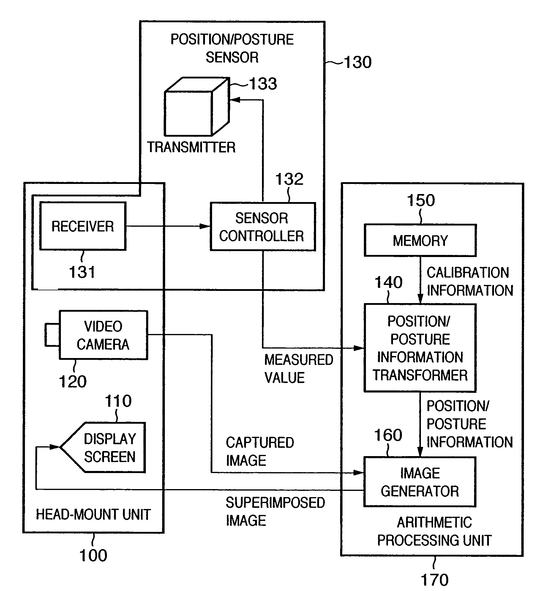
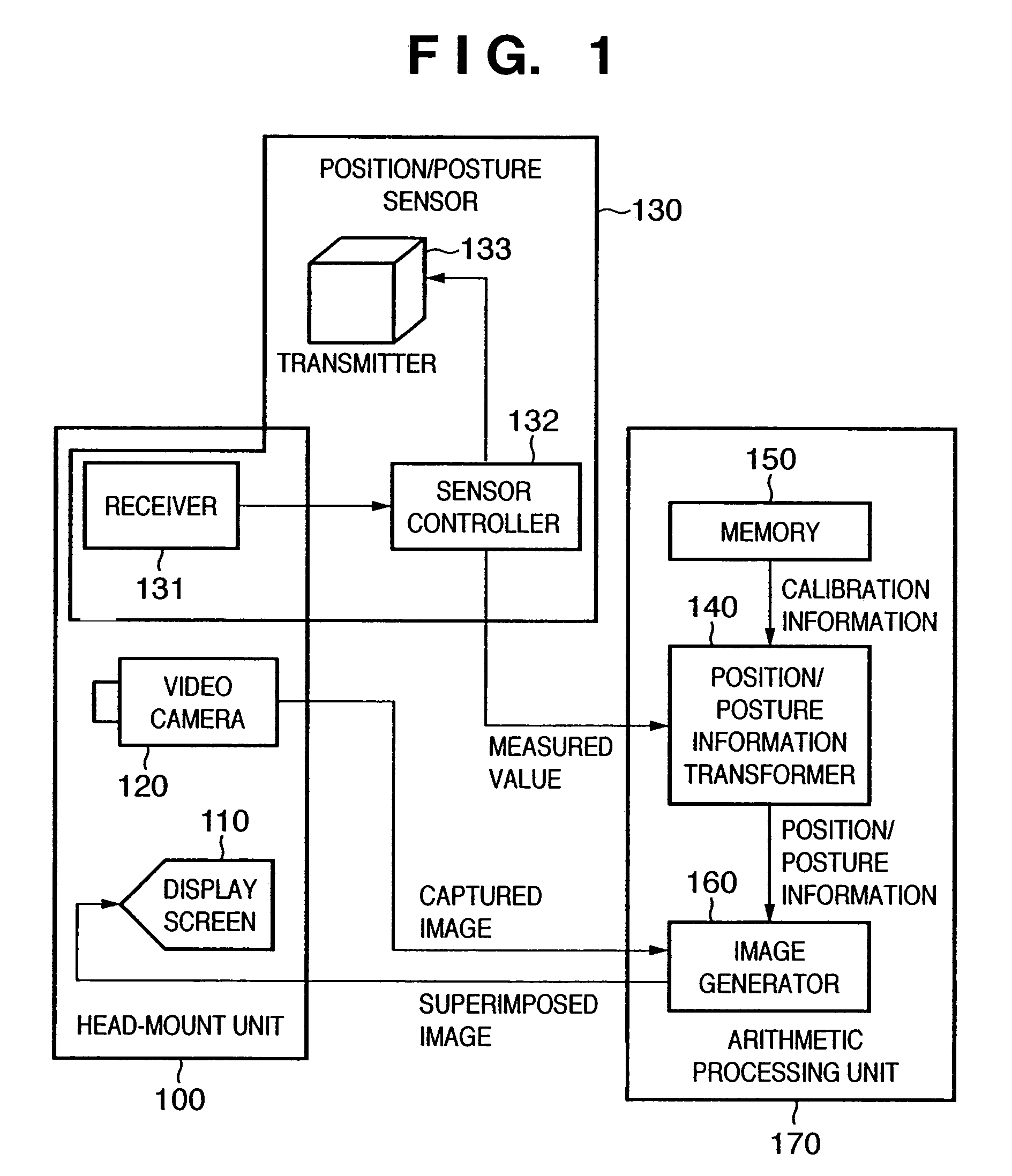
[0253]FIG. 21 is a schematic block diagram showing the arrangement of a sensor calibration apparatus according to the third embodiment. In the second embodiment, the display unit 5200 is arranged outside the head-mount unit 5300. In the third embodiment, the display unit 5200 is included in the head-mount unit 5300. Such arrangement can be implemented when a display device such as an HMD or the like that the user can wear on the head is used as the display unit 5200. In the third embodiment, since the head-wearable display device is used, the user of this apparatus can calibrate under the same condition as that upon using an image display apparatus which presents mixed reality.


PUM


Abstract

A calibration information calculation unit 340 calculates the first coordinate positions of feature points included in images obtained by an image sensing apparatus at timings from an instruction unit 350 using position data, on world coordinate system, of a plurality of feature points held by a world coordinate holding unit 310 and the measured values of a position/posture sensor 130 input to a data management unit 330 at the timings. The unit 340 receives the second coordinate positions, which are acquired by an image coordinate acquisition unit 320, of the feature points included in the images obtained by the image sensing device at the timings. The unit 340 calculates calibration information using the first and second coordinate positions.

Description

CROSS REFERENCE TO RELATED APPLICATION[0001]This application is a division of application Ser. No. 10 / 390,739, filed Mar. 19, 2003 now U.S. Pat. No. 6,792,370.FIELD OF THE INVENTION[0002]The present invention relates to a technique for calibrating a position / posture sensor, and a technique for obtaining parameters used upon transforming an output value of the position / posture sensor for the purpose of measuring the position and posture of an image sensing device using the position / posture sensor.BACKGROUND OF THE INVENTION[0003]In recent years, studies about mixed reality that aims at seamless joint of real and virtual spaces have been extensively made. An image display apparatus which presents mixed reality is implemented by superimposing an image of a virtual space (e.g., a virtual object, text information, and the like rendered by computer graphics) onto an image of a real space photographed by an image sensing device such as a video camera or the like.[0004]As applications of su...

Claims


Application Information

Patent Timeline
IPC IPC(8): G01C17/38G01C9/00G06K9/00G06T7/00
CPCG06T7/0018G06T7/0042G06T2207/30244G06T7/73G06T7/80
Inventor SATOH, KIYOHIDEUCHIYAMA, SHINJIKOBAYASHI, TOSHIHIRO
Owner CANON KK
Why Eureka
Try Eureka