Vacuum cleaner and suction nozzle employed therein

Active Publication Date: 2006-11-07
PANASONIC CORP
View PDF12 Cites 11 Cited by
  • Summary
  • Abstract
  • Description
  • Claims
  • Application Information

AI Technical Summary

Benefits of technology

[0008]It is, therefore, a primary object of the present invention to provide a floor nozzle and a mini nozzle for u

Problems solved by technology

Such an electric vacuum cleaner is capable of efficiently cleaning the floor with the wide surfaced floor nozzle 101, however, cleaning a surface that is smaller than the floor nozzle 101, e.g., when cleaning the stairs, creates a problem of using the floor nozzle 101.
However, the exchange of the suction heads is a great inconvenience to a user.
However, a height of the floor nozzle 210 of the conventional vacuum cleaner described above is high enough to be limited for usage thereof in a cleaning surface that h

Method used


Image

  • Vacuum cleaner and suction nozzle employed therein
  • Vacuum cleaner and suction nozzle employed therein
  • Vacuum cleaner and suction nozzle employed therein

Examples


Example

[0035]A first preferred embodiment will now be described with accompanying drawings. The preferred embodiments to be shown below are particular examples of the present invention and do not limit the technical scope of the present invention.

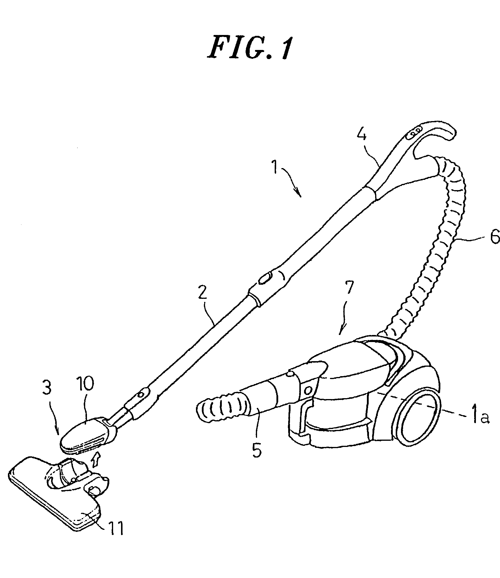
[0036]As illustrated in FIG. 1, the preferred embodiment pertains to a canister type electric vacuum cleaner 1 and a suction nozzle 3 serving as a suction inlet. The electric vacuum cleaner 1 is configured as shown below. There is detachably provided the suction nozzle 3 at a distal end portion of an extension tube 2 coupled with a handle (control unit) 4. A hose 6 coupled with the handle 4 is connected to a main body 7 of the electric vacuum cleaner via a hose joint 5. The main body 7 incorporates an electric blower 1a therein.

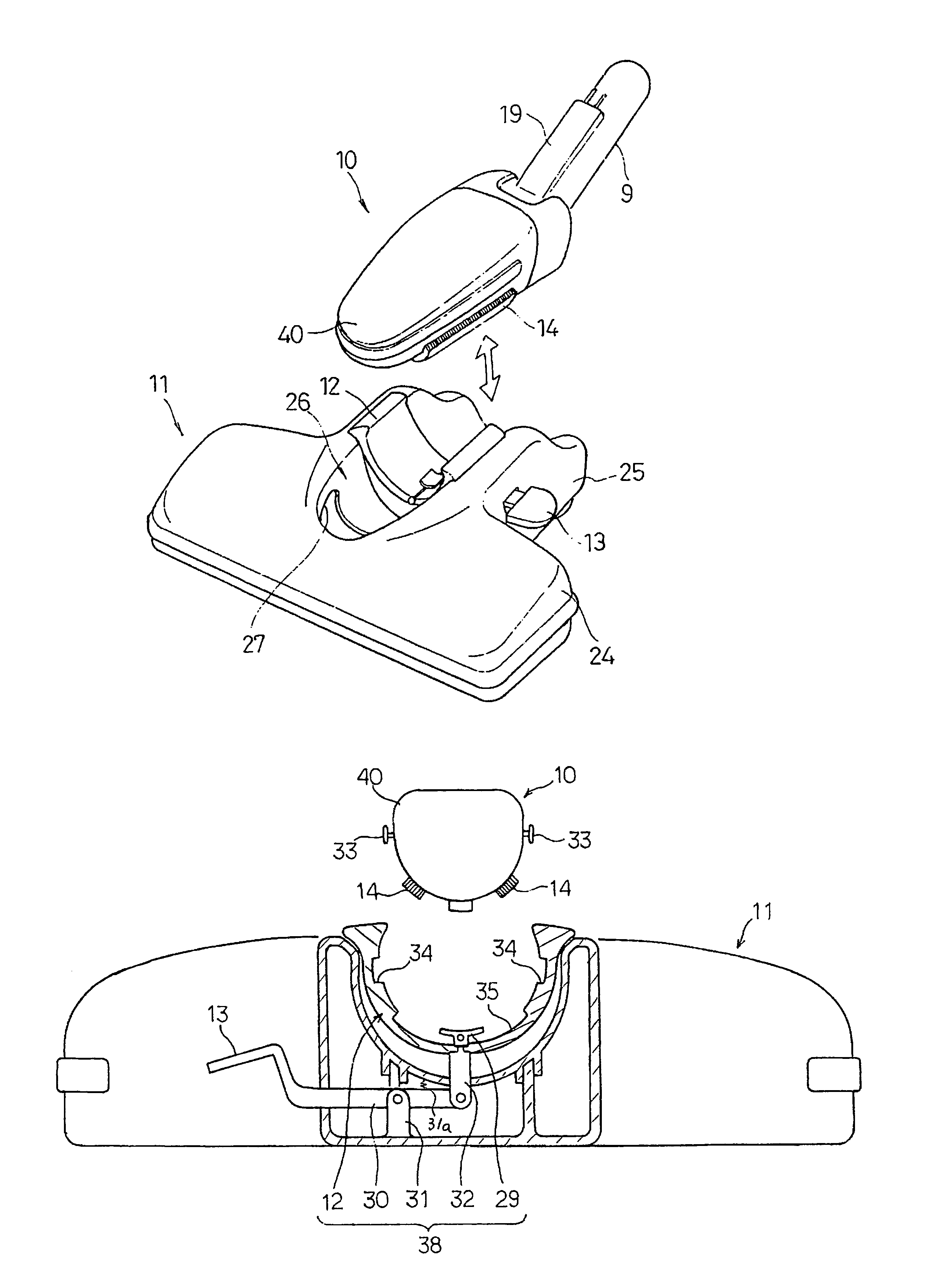
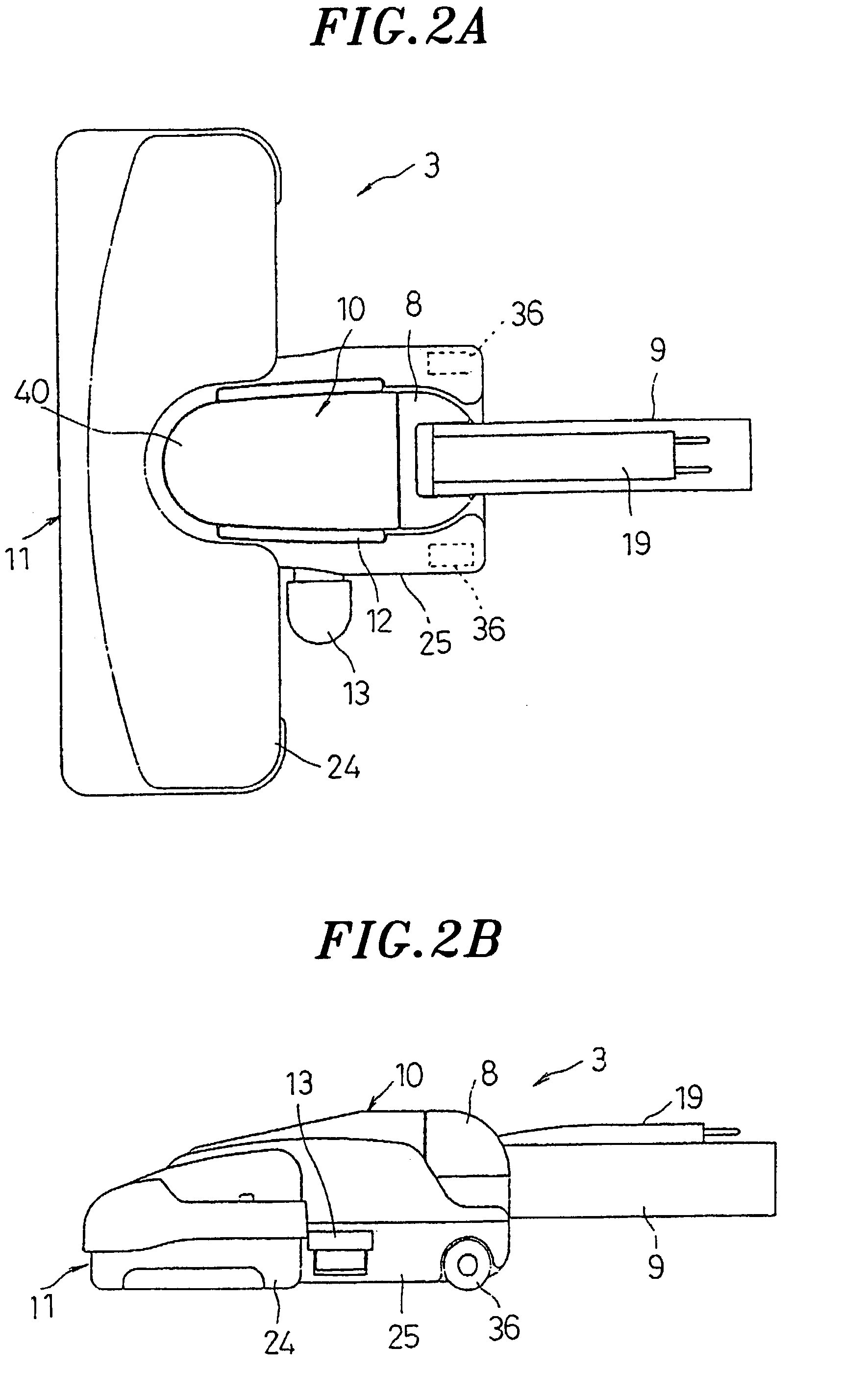
[0037]The suction nozzle 3 as illustrated in FIGS. 2A and 2B, includes a floor nozzle 11 and a mini nozzle 10 to be detachably secured onto the floor nozzle 11. The mini nozzle 10 incorporates a joint 9 connected with a suc...


PUM


Abstract

A suction nozzle for use in a vacuum cleaner includes a floor nozzle and a mini nozzle having a suction head, a rotatable joint, and joint, to be detachably secured in the floor nozzle. Either of the suction head and the rotatable joint or the rotatable joint and the joint is vertically joined and the other rotatably joined. Moreover, the suction head is unrotatably secured onto the floor nozzle, and forms an air communication with the floor nozzle.

Description

FIELD OF THE INVENTION[0001]The present invention relates to a suction nozzle employed in an electric vacuum cleaner; and, more particularly, to a floor nozzle incorporating a compact nozzle detachably attached thereto.BACKGROUND OF THE INVENTION[0002]FIG. 21 represents an exemplary canister type vacuum cleaner including an extension tube 102 detachably attached to a suction nozzle 101 in a front distal end thereof and further coupled to a handle 103 and a hose 104 which extends from the handle 103 is connected with a main body 106 via a joint 105. Such an electric vacuum cleaner is capable of efficiently cleaning the floor with the wide surfaced floor nozzle 101, however, cleaning a surface that is smaller than the floor nozzle 101, e.g., when cleaning the stairs, creates a problem of using the floor nozzle 101. In general, such surfaces are cleaned with crevice nozzles and brush nozzles that are equipped with the electric vacuum cleaner as supplements to the floor nozzle 101 by re...

Claims


Application Information

Patent Timeline
IPC IPC(8): A47L9/02A47L9/24A47L9/06A47L9/28
CPCA47L9/02A47L9/06A47L9/062A47L9/066A47L9/0673A47L9/242A47L9/2805A47L9/2842A47L9/2857
Inventor URATANI, HIROYUKISOEJIMA, MASAKUNIFUJITA, KOICHISHIBUYA, MASAKIIMAI, HIDETOSHITAKAHASHI, MASAKIFUKUSHIMA, MASAICHISENOO, HIROYUKI
Owner PANASONIC CORP
Why Eureka
Try Eureka