Self-adjusting snow plow

a snow plow and self-adjusting technology, applied in the field of adjustable snow plows, can solve the problems of individuals purchasing and using such a vehicle, difficulty in moving snow off open ground, and eventually affecting the use of open ground for pedestrian and vehicular travel, and achieves the effects of convenient use, quick and easy attachment to the front end of any vehicle, and moderate cos

Inactive Publication Date: 2006-11-07
AGRI COVER
View PDF40 Cites 43 Cited by
  • Summary
  • Abstract
  • Description
  • Claims
  • Application Information

AI Technical Summary

Benefits of technology

[0016]It is an additional objective of the present invention to provide such an apparatus that can be easily mounted and removed from the front end of pickup trucks, sport utility vehicles and other commonly used personal transit type vehicles, and that the apparatus for mounting the plow blade provides flexibility for mounting the plow blade at different relative heights with respect to vehicles that may stand at different relative heights off of the ground.
[0029]It is still another objective of the present invention to provide a mounting apparatus including two mounting uprights, the mounting uprights preferably including attachment members for securing the plow blade when the plow blade is not in use for snow plowing operations and the vehicle is used for transit purposes. It is a further object to provide attachment members that allow the plow blade to be easily lifted, one end at a time, and secured in the respective attachments members one end at a time, so that a single individual can easily lift the plow blade up into the non-operational use position without assistance.

Problems solved by technology

Moving snow off of open ground, streets, sidewalks and parking lots is an age-old problem in less temperate climates where significant snowfall is anticipated during colder periods of the year.
If the snow is allowed to accumulate over a period of weeks, the snow eventually makes the use of these surfaces for both pedestrian and vehicular travel difficult, if not treacherous.
The purchase and use of such a vehicle by individuals, however, who have a need to move or remove accumulated snow in smaller areas, such as driveways and privately owned parking areas, is less feasible.
First of all, the larger vehicles are expensive to purchase and maintain and are, in some cases, dedicated solely to the removal of accumulated snow.
It will be appreciated that it would not be cost effective for an individual to purchase, house and maintain such a vehicle for just removing snow from driveways and smaller parking lots during a limited period of the year.
Furthermore, these vehicles are difficult to operate and often require significant training or experience operating such vehicles.
Many of the snow plows attached to these vehicles, however, are large and heavy and are not easily attached and removed from the vehicles.
Although each of these inventions has its own advantages, none of them are easy to attach to or remove from the vehicle.
These snow plows also tend to be heavy and cumbersome, and at least somewhat unsightly if one is required, for practical reasons, to keep it attached to the vehicle 24 / 7 for a period of several months during the snow season.
In addition, the prior art snow plows are generally so heavy that they will not ride up when they are on open ground, for instance, but will tear up the ground and remove grass and other plant things often just because of the sheer weight of the plow as it passes along the ground surface.
Also, the prior art snow plows are often virtually impossible for a single person to handle, because of the weight associated with these plows; and plows that appear to be relatively light weight, such as the snow plow described by Knutson et al.
(U.S. Pat. No. 6,240,658), generally have multiple attachment points and do not appear to be highly effective, durable or marketable.

Method used


Image

  • Self-adjusting snow plow
  • Self-adjusting snow plow
  • Self-adjusting snow plow

Examples


Embodiment Construction

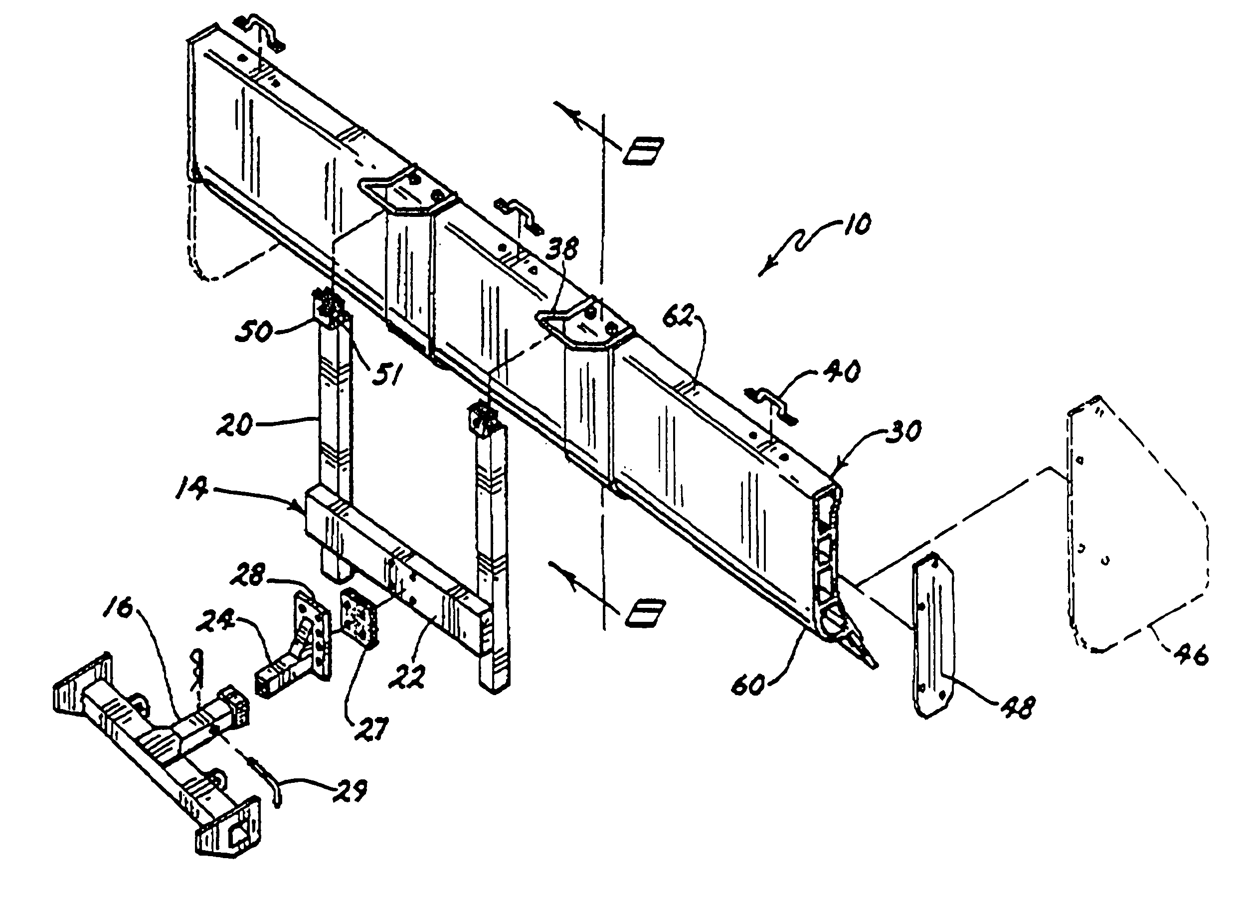
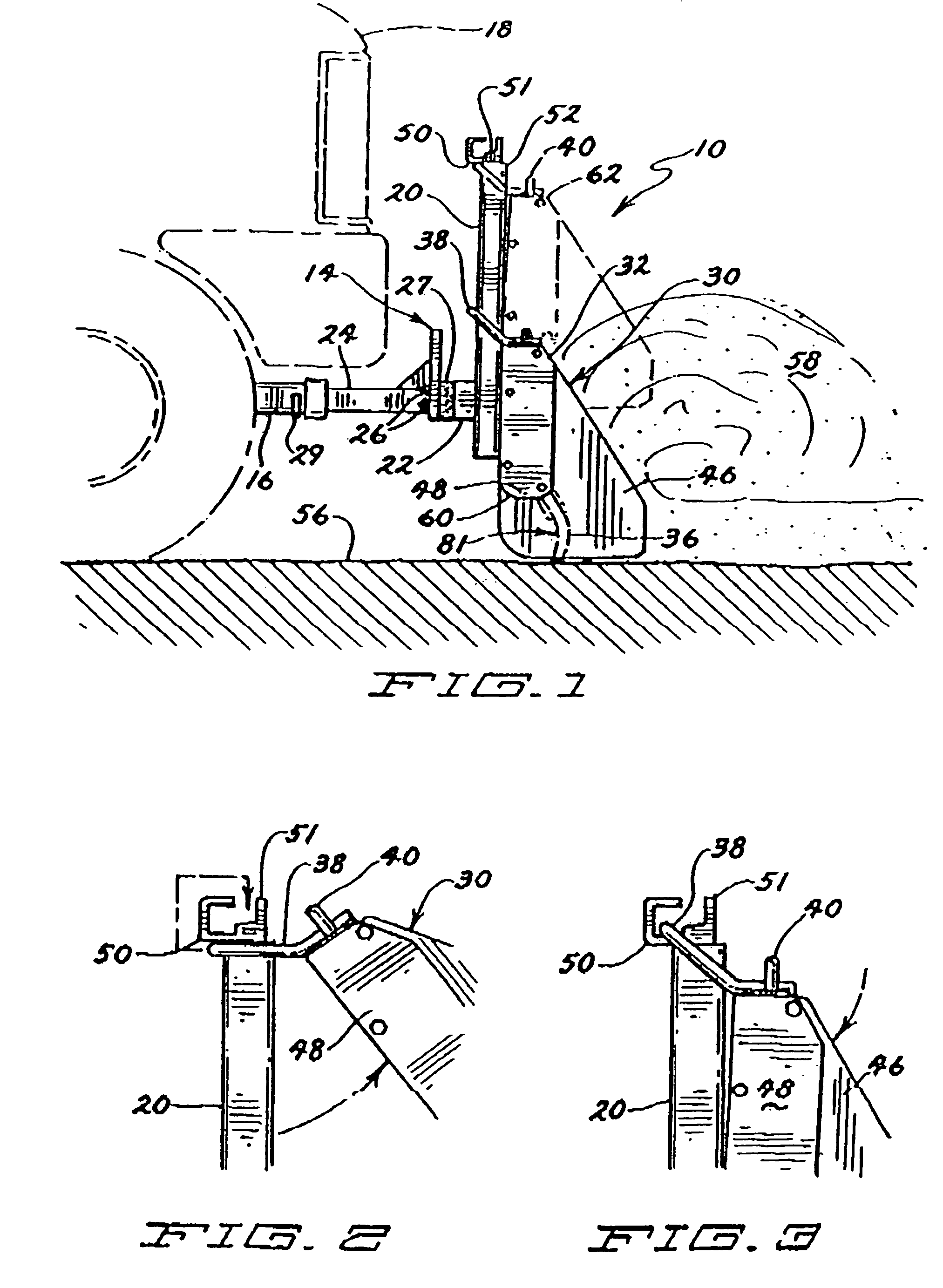
[0082]Referring now to the drawings, and more particularly, to FIGS. 1–3, an alternate embodiment of a self-adjusting snow plow 10 of the present invention is shown. The preferred snow plow 10 includes a mounting apparatus 14 and a plow blade 30. The mounting apparatus 14 includes two mounting uprights 20 that are interconnected by an interconnecting member 22. In this embodiment, a hitch tongue 24 is secured to the interconnecting member 22. The hitch tongue 24 is secured to the interconnecting member 22 with a resilient rubber connecting member 27 interspersed between the interconnecting member 22 and a flat connecting plate 28 of the hitch tongue 24. A hitch tongue securing pin 29 secures the hitch tongue 24 in a hitch receiver 16, which is secured to a vehicle 18 (partially shown in phantom in FIG. 1). The resilient rubber connecting member 27 allows the entire snow plow 10 some flexibility when the plow blade 30 is subjected to great forces. This is believed to reduce the shock...


PUM


Abstract

A self-adjusting snow plow for use with pickup trucks and sport utility vehicles is disclosed. The snow plow includes a mounting apparatus for attachment to a vehicle and a plow blade having first and second ends, a top, a bottom, a plurality of retention members and a rubber scraper. The mounting apparatus preferably includes a pair of mounting uprights and a hitch tongue which is easily mounted in a hitch receiver which is secured to the front of a vehicle. The retention members are preferably constructed and arranged to at least partially encircle and slideably engage one of the respective mounting uprights and the retention members allow the respective ends of the plow blade to slide upward relative to the mounting upright most proximate to that end of the plow while the other end of the plow remains generally in the same position relative to the mounting upright proximate that end of the plow blade. The preferred retention members also permit the bottom of the plow blade to pivot away from the respective mounting uprights when the plow blade is engaged with the mounting apparatus in a working orientation and the vehicle is in motion in a direction rearward of the plow blade.

Description

RELATED APPLICATIONS[0001]The present application is related to and claims priority to both U.S. patent application Ser. No. 10 / 404,164, filed Mar. 31, 2003, now issued as U.S. Pat. No. 6,817,118 and co-pending U.S. patent application Ser. No. 10 / 841,740, filed May 7, 2004, both entitled Self-Adjusting Snow Plow, which claim priority to PCT application No. PCT / US01 / 47125 for SELF-ADJUSTING SNOW PLOW filed Nov. 12, 2001, each of which are hereby incorporated herein by reference. The present application is also related to co-pending U.S. patent application Ser. No. 10 / 990,148, filed Nov. 15, 2004.FIELD OF THE INVENTION[0002]The present invention relates to adjustable snow plows for attachment to land vehicles, primarily personal utility vehicles such as pickup trucks and sport utility vehicles.BACKGROUND OF THE INVENTION[0003]Moving snow off of open ground, streets, sidewalks and parking lots is an age-old problem in less temperate climates where significant snowfall is anticipated du...

Claims


Application Information

Patent Timeline
Patent Type & Authority Patents(United States)
IPC IPC(8): E01H5/04E01H5/06
CPCE01H5/06E01H5/061
Inventor SCHMEICHEL, CHARLES M.
Owner AGRI COVER
Why Eureka
Try Eureka