Comminution blade

Inactive Publication Date: 2006-11-07
BADGER SHREDDING PROD
View PDF23 Cites 8 Cited by
  • Summary
  • Abstract
  • Description
  • Claims
  • Application Information

AI Technical Summary

Benefits of technology

[0008]The present invention provides a blade assembly which is able to not only efficiently burst, but also efficiently shear materials presented to it. Most notably, a machine of the invention can reduce not only bricks and small pieces of concrete, but also larger pieces of concrete and concrete containing rebar and / or steel cable. A machine of the invention can also reduce other materials such as wood, glass, asphalt, and almost any other material which is either burstable or shearable or both.
[0015]In practicing the invention, each separate tooth or wear plate is individually fastened to the carrier by structure on the tooth or wear plate which cooperates with structure on the carrier to secure the tooth or wear plate with a pin and spring washer or a securing pin and bolt. The fasteners do not undergo any direct loading from the forces of comminution, and are therefore only subjected to relatively low forces to retain the teeth and wear plates in position. In addition, the pins and washers have no threads and are largely unexposed, except at the ends of the pin, so that they can be easily removed to remove worn teeth or wear plates from the carrier.

Problems solved by technology

As such, the blades are subjected to great forces and accordingly to intense wear.
As a result, the size of the pieces which could be reduced was limited.
Such machines worked for smaller materials, such as bricks, but did not work well for larger materials such as larger pieces of concrete or concrete containing rebar and / or cable.
A problem with these attachment systems is that fine particles of the material being comminuted becomes trapped in the threads, making it difficult to replace the teeth and wear plates.

Method used


Image

  • Comminution blade
  • Comminution blade
  • Comminution blade

Examples


Embodiment Construction

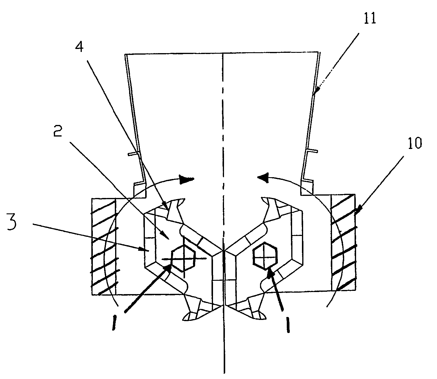
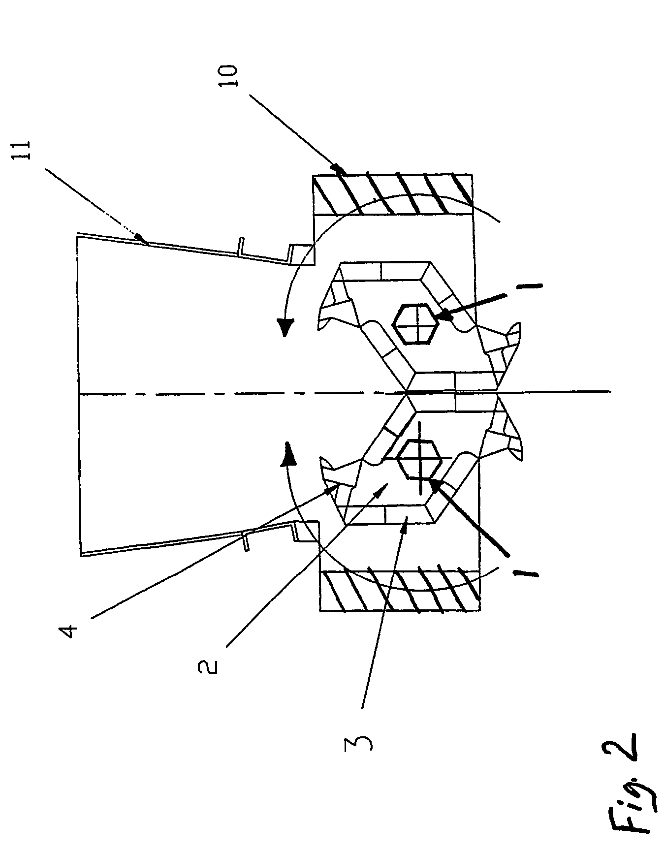
[0050]Referring to FIG. 2, the frame 10 may be fitted with a hopper 11 for feeding materials (not shown) to be comminuted to the pair of counter rotating blade assemblies. Also as shown in FIG. 2, it can be seen that the spacing of the shafts 1 is such that a significant amount of radial overlap is provided between the blades as they rotate. In general, the spacing is such that the teeth 4 just barely clear the spacer rings 5 as they rotate. The same is true of the spacing between the sides of adjacent interleaved blades 2, which are close together so as to effect efficient shearing of shearable materials presented to the shear edges of the teeth, receding surfaces and trailing surfaces. As is typical, the blades 2 may be arranged helically on each shaft, so that only one set of adjacent blades pass each other at any one instant in time, so that the torque of the counter-rotating shafts can be concentrated at one set of blades, and so that materials tend to flow axially toward one e...


PUM


Abstract

A blade (2) for a comminution machine of the type having interleaved counter-rotating blades (2) in the case of two shafts (1) or a single set of blades in the case of a single rotating shaft includes a carrier (20) with replaceable teeth (4) and wear plates (3). Each tooth (4) has to tooth tip (121) which projects from it and terminates in a bursting point (121), a forwardly raked receding surface (137) which recedes inwardly from the base of the tooth tip (121) and a receding surface (24) on the wear plates (3A, 3B) which extends inwardly from the base of the tooth (4) to a corner (9) at which it meets a trailing surface (24) on other wear plates (3C, 3D). Shear edges (83) are provided on the teeth (4), on the receding surfaces (24) where they meet the sides (22) of the wear plates (3A, 3D) and on the trailing surfaces where they meets the sides (22) of the wear plates (3C, 3D), and additional bursting points (149) may be provided on the receding surfaces. Two teeth (4) and associated receding and trailing surfaces are provided on each blade (2). The teeth (4) and wear plates (3) are connected to the carrier (20) using fasteners (56, 163) which are not subjected to significant forces of comminution.

Description

CROSS-REFERENCE TO RELATED APPLICATION[0001]This claims the benefit of U.S. Provisional Patent Application No. 60 / 244,828 filed Oct. 30, 2000.STATEMENT CONCERNING FEDERALLY SPONSORED RESEARCH OR DEVELOPMENT[0002]Not applicable.FIELD OF THE INVENTION[0003]This invention relates to blades for shredders, mineral reducers, and other types of comminution machines, and in particular to the construction and attachment of teeth or wear plates to a tooth carrier of a blade for a comminution machine.BACKGROUND OF THE INVENTION[0004]Referring to FIG. 1, a comminution machine, which may also be referred to as a shredder or a mineral reducer, typically includes at least one shaft of polygonal (as illustrated) or keyed section to transmit high torque at low speed mounted by bearings 6 on a frame 10 and driven by a reduction gearbox 8 or hydraulic motor. The frame 10 has two vertical side walls and two vertical end walls which together form a rectangular shape having the top and bottom open. Clean...

Claims


Application Information

Patent Timeline
IPC IPC(8): B02C18/16B02C18/14B02C18/18
CPCB02C18/142B02C18/184B02C2201/02
Inventor ROGERS, TERRY
Owner BADGER SHREDDING PROD
Why Eureka
Try Eureka