Support layer for thin copper foil

a support layer and copper foil technology, applied in the field of copper foil, can solve the problems of blisters on the surface of copper foil layer, and regions of laminate that are unacceptable for fine-line circuit processing

Inactive Publication Date: 2006-11-07
GBC METALS LLC
View PDF14 Cites 19 Cited by
  • Summary
  • Abstract
  • Description
  • Claims
  • Application Information

AI Technical Summary

Benefits of technology

[0017]Use of these alloys is effective to reduce the number of blisters that form, particularly in those applications where blisters are prone to form, such as lamination in the absence of pressure. The mechanism that causes a reduction in blistering is not known. It is believed that one or more of the following cause a reduction in blistering: when alloyed with the support layer material, the reactive elements increase the tensile strength of the support layer such that there is less flexing during processing; when alloyed with the support layer material, the reactive elements change the coefficient of thermal expansion of the support layer; and when either alloyed with the support layer material or coated on a surface of the support layer, the substrate alloy or its constituent phases react with gaseous elements or compounds such as moisture that may form at the release layer interface to suppress blister formation. For example, hydrogen if evolved, would dissolve in the substrate or react to form a hydride by combination with a reactive element. The alloying elements to provide these beneficial effects are preferably selected from the group consisting of titanium, zirconium, barium, magnesium, silicon, niobium, calcium and mixtures thereof.
[0018]The reactive alloying elements are present in an amount, by weight, of from 0.001% to 50% and preferably in an amount of from 0.1% to 5%. It is desired for there to be a sufficient quantity to provide the copper alloy with a tensile strength in excess of 30 ksi after being exposed to a lamination temperature of in excess of 180° C. This facilitates handling of the composite material, protects the thin copper foil layer from wrinkles and mechanical damage and can be used as a protective sheet in the circuit board fabrication process, such as for hole punching.

Problems solved by technology

One such defect that has been reported is blisters on the surface of the copper foil layer that previously contacted the support layer.
These small depressions render those regions of the laminate unacceptable for the processing of fine-line circuits.

Method used


Image

  • Support layer for thin copper foil
  • Support layer for thin copper foil
  • Support layer for thin copper foil

Examples


example

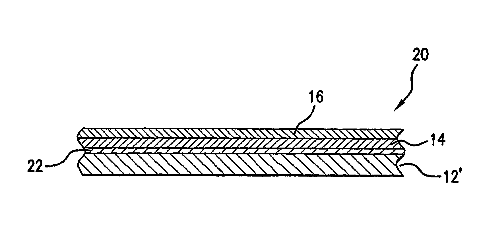
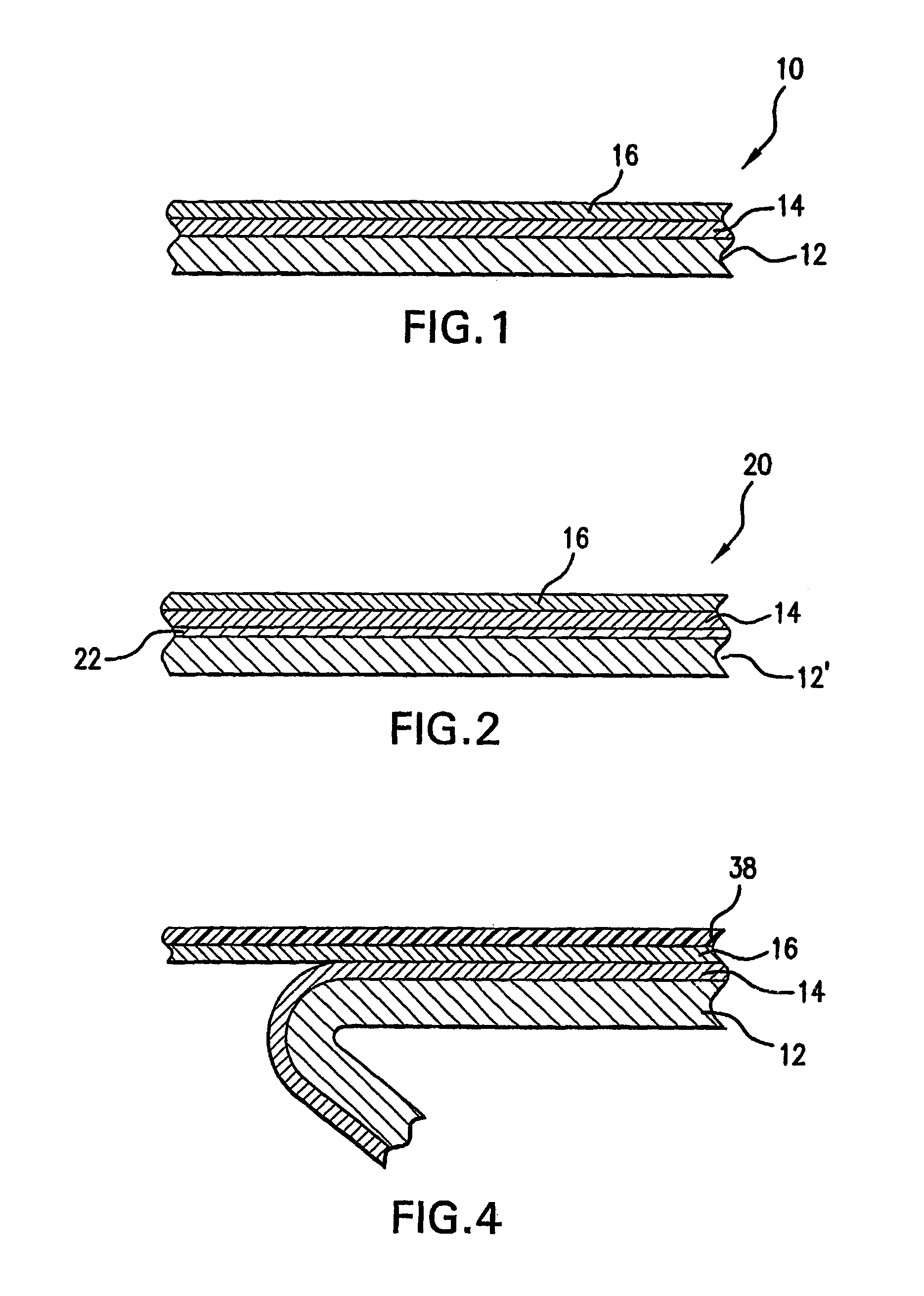
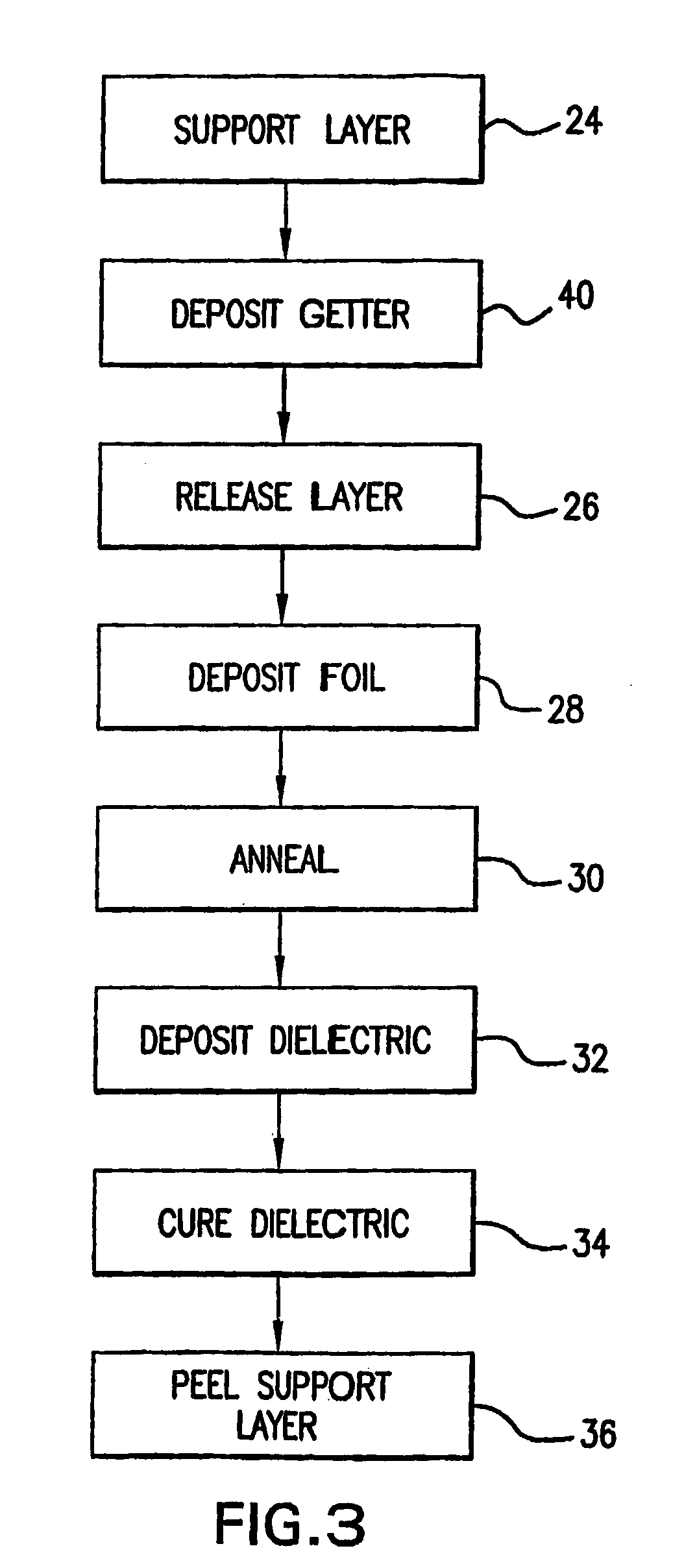
[0029]Support layers having the compositions and thicknesses recited in Table 1 were coated with a release layer having a thickness of between about 12 Å and about 200 Å and a nominal composition that was a mixture of chromium oxides, chromium, and chromium hydroxides. The release layer was deposited by electrodeposition. A copper foil layer having a nominal thickness of 5 μm was deposited by electrodeposition. The so-formed composite was then heated to 170° C. in an air, nitrogen or forming gas atmosphere for the time recited in Table 1.

[0030]The annealed samples were then heated to 360° C. for 30 minutes in a nitrogen atmosphere to simulate a cure cycle for a dielectric. The occurrence and density of blisters was then rated qualitatively to anticipate the quality of imaged copper foil circuit traces on a circuit board, where: 00=excellent; 0=good; Δ=fair; X=poor; and N.R.=not rated. The results are reported in Table 1.

[0031]

TABLE 1Rating following a heat treatment for theSupportsp...


PUM

PropertyMeasurementUnit
thicknessaaaaaaaaaa
thicknessaaaaaaaaaa
yield strengthaaaaaaaaaa

Abstract

A composite material useful for the manufacture of a circuit has a support layer, a metal foil layer having opposing first and second sides and a thickness of 15 microns or less and a release layer effective to facilitate separation of the metal foil layer from the support layer, the release layer disposed between and contacting both the support layer and the metal foil layer. A reactive element containing layer, which may be the support layer, effective to react with gaseous elements or compounds to form thermally stable compounds contacts the release layer. The composite material is preferably subjected to a low temperature heat treatment. The combination of the low temperature heat treatment and the reactive element containing layer results in reduced defects including blisters in the copper foil during subsequent processing.

Description

CROSS REFERENCE TO RELATED PATENTS[0001]This patent application relates to and claims priority to U.S. Provisional Patent Application Ser. No. 60 / 513,367 for “Support Layer for Thin Copper Foil” that was filed on Oct. 22, 2003. In addition, this patent application relates to U.S. Pat. No. 6,346,335, “Copper Foil Including a Release Layer” and U.S. Pat. No. 6,569,543, “Copper Foil with Low Profile Bond Enhancement.” The subject matters of the provisional patent application and both United States patents are incorporated by reference herein in their entireties.BACKGROUND OF THE INVENTION[0002]1. Field of the Invention[0003]This invention relates to a copper foil for use in the manufacture of printed circuit boards and flexible circuits. More particularly, a composite material includes a copper foil layer and a support layer with a release layer disposed between the copper foil and the support layer. Contacting the release layer with a reactive element at an elevated temperature reduce...

Claims


Application Information

Patent Timeline
Patent Type & Authority Patents(United States)
IPC IPC(8): B32B15/01B32B15/04B32B15/20C23C26/00C23C28/00C25D7/06H05K3/02
CPCC23C26/00C25D7/0614H05K3/025H05K2203/1105Y10T428/12438Y10T428/12514Y10T428/12Y10T428/12493Y10T428/12903Y10T428/265Y10T428/1291B32B15/04B32B15/20C23C28/00H05K3/02
Inventor BRENNEMAN, WILLIAM L.CHEN, SZUCHAIN F.
Owner GBC METALS LLC
Why Eureka
Try Eureka