Battery pack

Inactive Publication Date: 2006-11-07
GK BRIDGE 1
View PDF5 Cites 11 Cited by
  • Summary
  • Abstract
  • Description
  • Claims
  • Application Information

AI Technical Summary

Benefits of technology

[0011]In the battery pack, the laminate battery is inserted into the plastic frame having both open surfaces to thereby form the framed battery unit, and both surfaces of the framed battery unit are covered by the metal plates. Therefore, the battery pac

Problems solved by technology

However, the polymer battery has a drawback due to the lack of the metal sheathing case.
Namely, since the strength of the sheathing film is weaker than the metal case, a front surface of the polymer battery is more likely to be damaged.
In the battery pack with the aforementioned structure, although both surfaces of the polymer battery can be protected by the metal plates, there is a drawback in that the overall battery pack becomes thick.
Since it is important that the polymer battery can be made thin, if the overall thickness is increased,

Method used


Image

  • Battery pack
  • Battery pack
  • Battery pack

Examples


Embodiment Construction

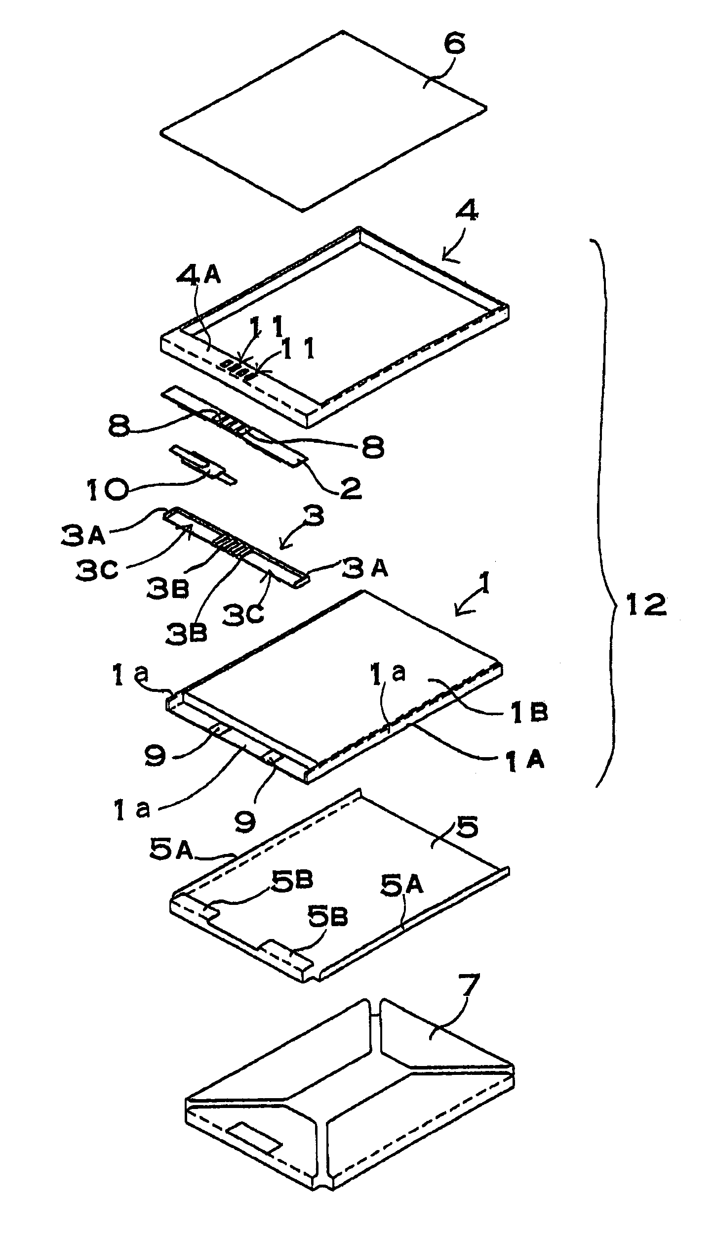
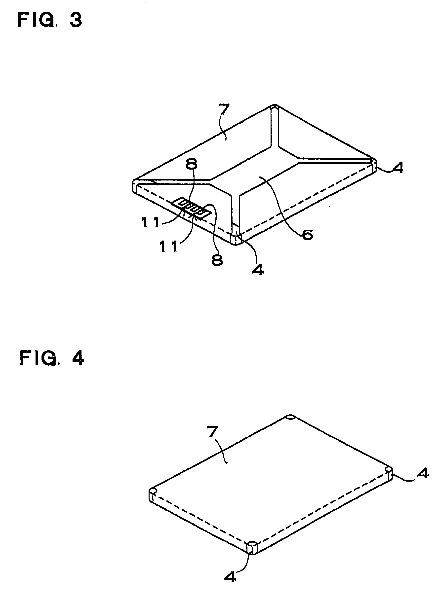
[0027]A battery pack shown in FIG. 3 to FIG. 11 includes a polymer battery 1, 81, 101, 111; a terminal substrate 2, 82 disposed at a lap section 1a of the polymer battery 1, 81, 101, 111; a substrate holder 3, 83 provided between the terminal substrate 2, 82 and the lap section 1a, 81a; a plastic frame 4, 84, 104, 114 in which the polymer battery 1, 81, 101, 111 is fittingly inserted; a first metal plate 5, 85, 105, 115 and a second metal plate 6, 86, 106, 116 which cover both surfaces of the polymer battery 1, 81, 101, 111; and a label 7, 87, 107, 117 which adheres to the front surfaces of the metal plates.

[0028]In the following embodiments, structural elements which are the same as in embodiments shown in FIGS. 3 through 6, are numbered the same lower order digits in embodiments shown in FIGS. 7 through 9 except for the highest order digit, and in embodiments shown in FIGS. 10 through 11 except for the two highest order digits, their description is abbreviated.

[0029]In the polymer...


PUM


Abstract

A battery pack includes a laminate battery having a built-in electrode held inside thereof by connecting a first sheathing film and a second sheathing film at lap sections thereof along outer peripheries of the electrode. A terminal substrate is disposed at the lap section and includes output terminals at a front surface side thereof. A substrate holder is disposed between a rear surface of the terminal substrate and the lap section, and a first metal plate is laminated on a first sheathing film side of the laminate battery. In the battery pack, the terminal substrate is supported by the substrate holder, the lap section, and the first metal plate, and the output terminals of the terminal substrate are disposed at positions so as to be brought closer to the same plane as a front surface of the second sheathing film.

Description

[0001]This application is based on Application No. 2002-191441 filed in Japan on Jun. 28, 2002, the content of which is incorporated hereinto by reference.BACKGROUND OF THE INVENTION[0002]The present invention relates to a battery pack including a polymer battery.[0003]A polymer battery is manufactured by laminating sheathing films on both surfaces of an electrode and airtightly connecting the sheathing films at a circumference of the electrode. The polymer battery with this structure has an advantageous feature in that the polymer battery can be made thinner and bigger as compared to a battery in which an electrode is inserted in a metal sheathing case. However, the polymer battery has a drawback due to the lack of the metal sheathing case. Namely, since the strength of the sheathing film is weaker than the metal case, a front surface of the polymer battery is more likely to be damaged. In order to solve this adverse effect, there has been developed a battery pack in which a polyme...

Claims


Application Information

Patent Timeline
IPC IPC(8): H01M2/02H01M2/30H01M10/04H01M50/296
CPCH01M2/0207H01M10/0436H01M2/30Y02E60/10Y02P70/50H01M50/296
Inventor MORITA, HIDEYOOONO, YASUHIRO
Owner GK BRIDGE 1
Why Eureka
Try Eureka