Optical carriage of scanner and method for the same

Inactive Publication Date: 2006-11-07
INTELLECTUAL VENTURES I LLC
View PDF2 Cites 4 Cited by
  • Summary
  • Abstract
  • Description
  • Claims
  • Application Information

AI Technical Summary

Benefits of technology

[0008]One main object of the invention is to provide an optical carriage of scanner, moreover, the provided invention have the following advantages such as low cost, low errors, simply fabrication, and high precision.
[0012]In this embodiment, the mirror assembly is mechanically connected with the element assembly. In fact, each assembly is formed and precisely amended before they are connected to form the whole optical carriage of scanner. Besides, to reduce the risk of deformation of both lens holders and supporters, the embodiment forms both lens holders and supporters by one or combination of the following: metal punch, plastic ejection, and plastic process.

Problems solved by technology

However, because that the result of the plastic ejection is strongly dependent on the fabrication conditions which would be changed during the fabrication of different plastic ejection, the shape of the different optical carriages is hard to be exact similar.
Further, because the whole optical carriage is formed at the same time, it is difficult to separately amend the details of the optical carriage.
Thus, the shape and the position of the real supporters usually are different to the predetermined supporter, and both mirrors deviation and wrong propagation path of light are unavoidable.
Moreover, because that the hardness and the rigidity of the plastic material is weak, because that the weight of the mirror is irnegligible, and because the supporters suffer extra stress during the moving process of the optical carriage, the supporters would be damaged and / or deformed even the fabrication is thorough prefect, and both mirrors deviation and wrong propagation path of light are unavoidable.

Method used


Image

  • Optical carriage of scanner and method for the same
  • Optical carriage of scanner and method for the same
  • Optical carriage of scanner and method for the same

Examples


Embodiment Construction

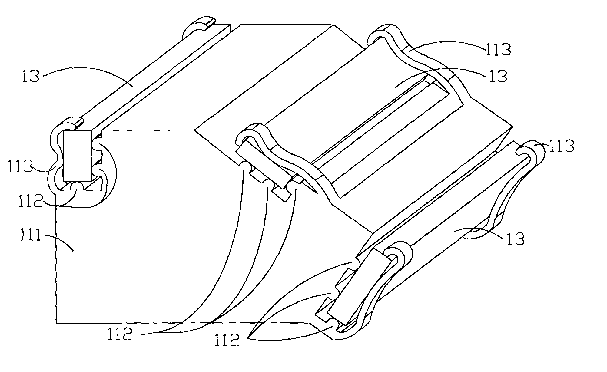
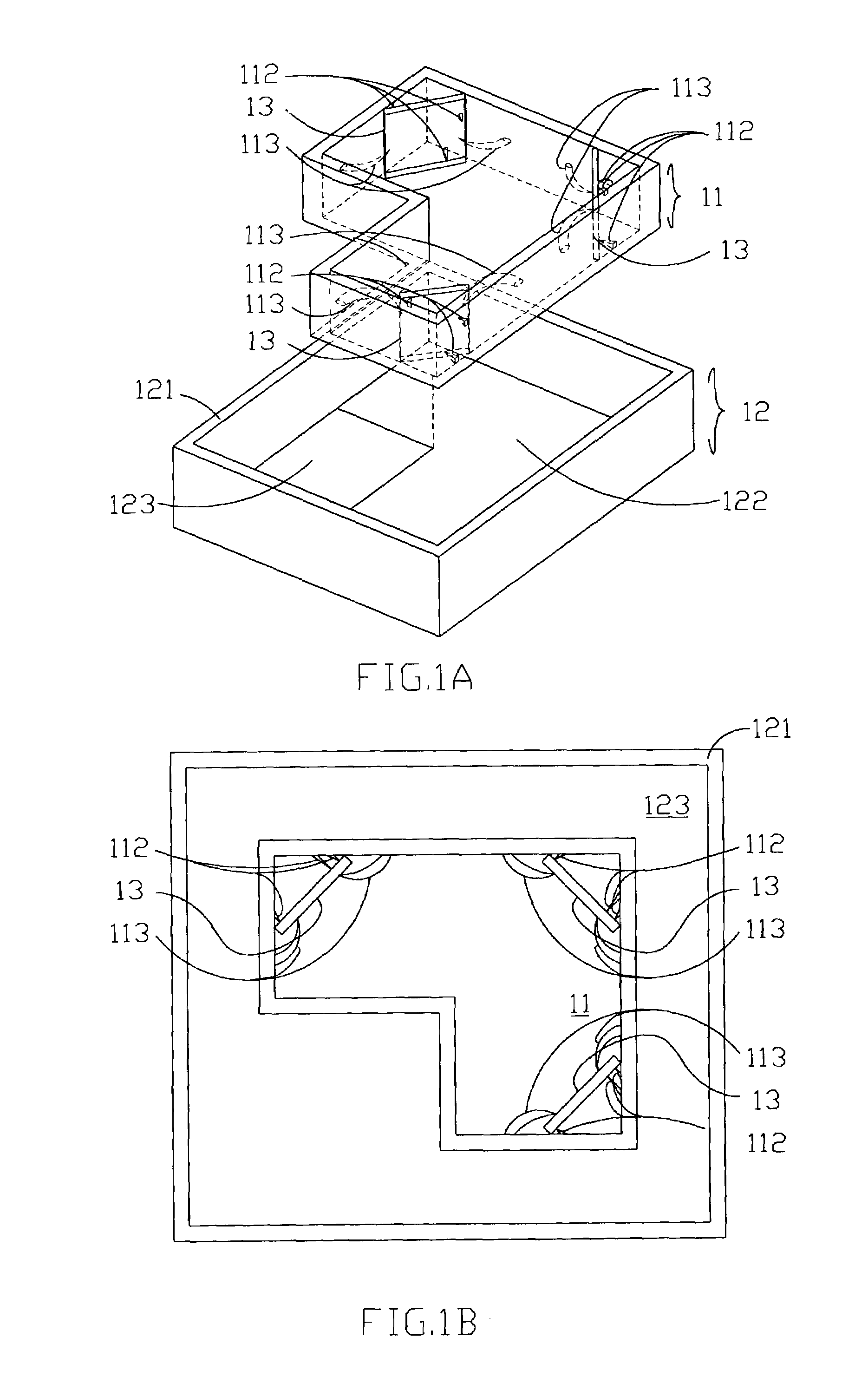
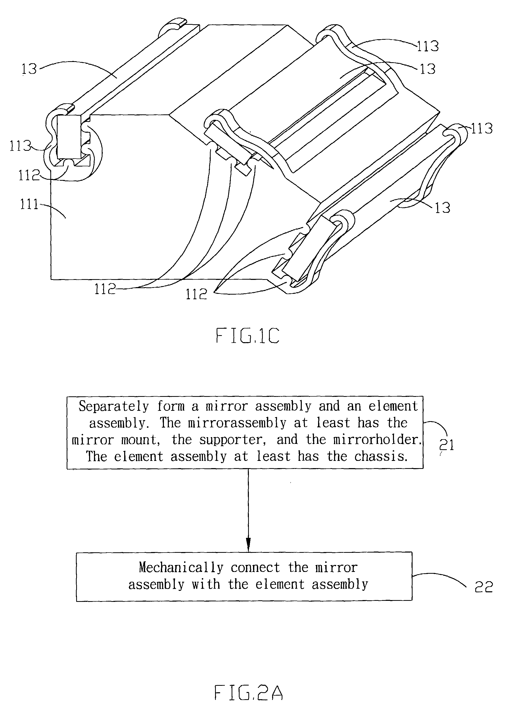
[0016]Regarding to the defects induced by the process that directly form the whole structure plastic ejection, and also regarding to the defects induced by the lack of separated amendment of the details, the invention solves the defects by a two-stage formation. In detail, the invention separately forms the mirror assembly and the element assembly without limiting how each assembly is formed, and then mechanically connects the mirror assembly with the element assembly. Thus, any defect induced by the plastic ejection could be prevent while the plastic ejection being replaced by other fabrication, and the details of each assembly could be separately amended during the formation of each assembly. Besides, because the mirror assembly and the element assembly do not share the same device for the conventional optical carriage of scanner, the two-stage formation of this invention not only would not change the structure and corresponding position of the assemblies, but also would not induc...


PUM


Abstract

An optical carriage of scanner has a mirror assembly and a device assembly, the mirror assembly has a mirror mount, some mirror holder, and some supporters, and the device assembly has a chassis. In this invention, the mirror assembly and the device assembly are mechanically connected after separately formation. Further, to ensure correct shape of these mirror holders and these supporters, they could be formed by metal punch, plastic ejection, or plastic process.

Description

BACKGROUND OF THE INVENTION[0001]1. Field of the Invention[0002]This invention generally relates to the optical carriage of scanner and method for forming the same, moreover, the invention relates to the following issues: reduces errors, simplifying construction, reducing cost and increasing precision.[0003]2. Description of the Prior Art[0004]The conventional scanner usually locates some mirrors in an optical carriage, thus, the location of the mirrors could be changed to achieve some predetermined functions by moving the optical carriage. Further, the mirror mount usually is a combination of an element assembly, which has a chassis, and a mirror assembly, which has a mirror mount and a support device. Herein, the mirror assembly is used to modify the propagation path of the light, and the element assembly is used to carry some elements for processing the light.[0005]For example, the conventional scanner usually puts some mirrors in and on an optical carriage, and acquires the comp...

Claims


Application Information

Patent Timeline
IPC IPC(8): H04N1/04H04N1/024
CPCH04N1/024H04N2201/0246H04N2201/02487H04N2201/02474H04N2201/02481H04N2201/02483
Inventor CHEN, TSUNG-YINHSIAO, CHUN-I
Owner INTELLECTUAL VENTURES I LLC
Why Eureka
Try Eureka