
Method and apparatus for temporarily varying a parameter in an implantable medical device

a medical device and parameter technology, applied in the field of methods and apparatus, can solve the problems that the pacemaker or the pacemaker/cardioverter/defibrillator does not address the benefit of having periods of elevated pacing designed into the pacemaker

Active Publication Date: 2006-11-07
MEDTRONIC INC
View PDF52 Cites 55 Cited by
  • Summary
  • Abstract
  • Description
  • Claims
  • Application Information

AI Technical Summary

Benefits of technology

The present invention is about a method and device for adjusting parameters in an implantable medical device that stimulates heart tissue and senses cardiac signals. The device measures the intervals between sensed cardiac signals and adjusts the parameters accordingly to achieve a target heart rate. The device can also select an exercise time profile based on the measured heart rate variability. The technical effects of this invention include improved accuracy and efficiency in adjusting parameters and better selection of exercise time profiles for patients.

Problems solved by technology

There is a growing population of patients having implantable pacemaker or pacemaker / cardioverter / defibrillator devices who are largely sedentary and who are therefore likely to be paced at their basal rate for much of the day, since they are unable to achieve any measurable amount of exercise on their own.
However, since current adaptive rate pacemakers or pacemaker / cardioverter / defibrillators are designed to find a range of natural rhythms occurring in the patient, whether to slow them during sleep, or to increase the rate during physical activity, with the goal of sensing and establishing a pacing rate within a controlled range of preexisting rates, currently available pacemakers or pacemaker / cardioverter / defibrillators do not address the benefit of having periods of elevated pacing designed into the pacemaker, particularly where no natural rhythm for the elevated pacing rate has been established.

Method used


Image

  • Method and apparatus for temporarily varying a parameter in an implantable medical device
  • Method and apparatus for temporarily varying a parameter in an implantable medical device
  • Method and apparatus for temporarily varying a parameter in an implantable medical device

Examples


Embodiment Construction

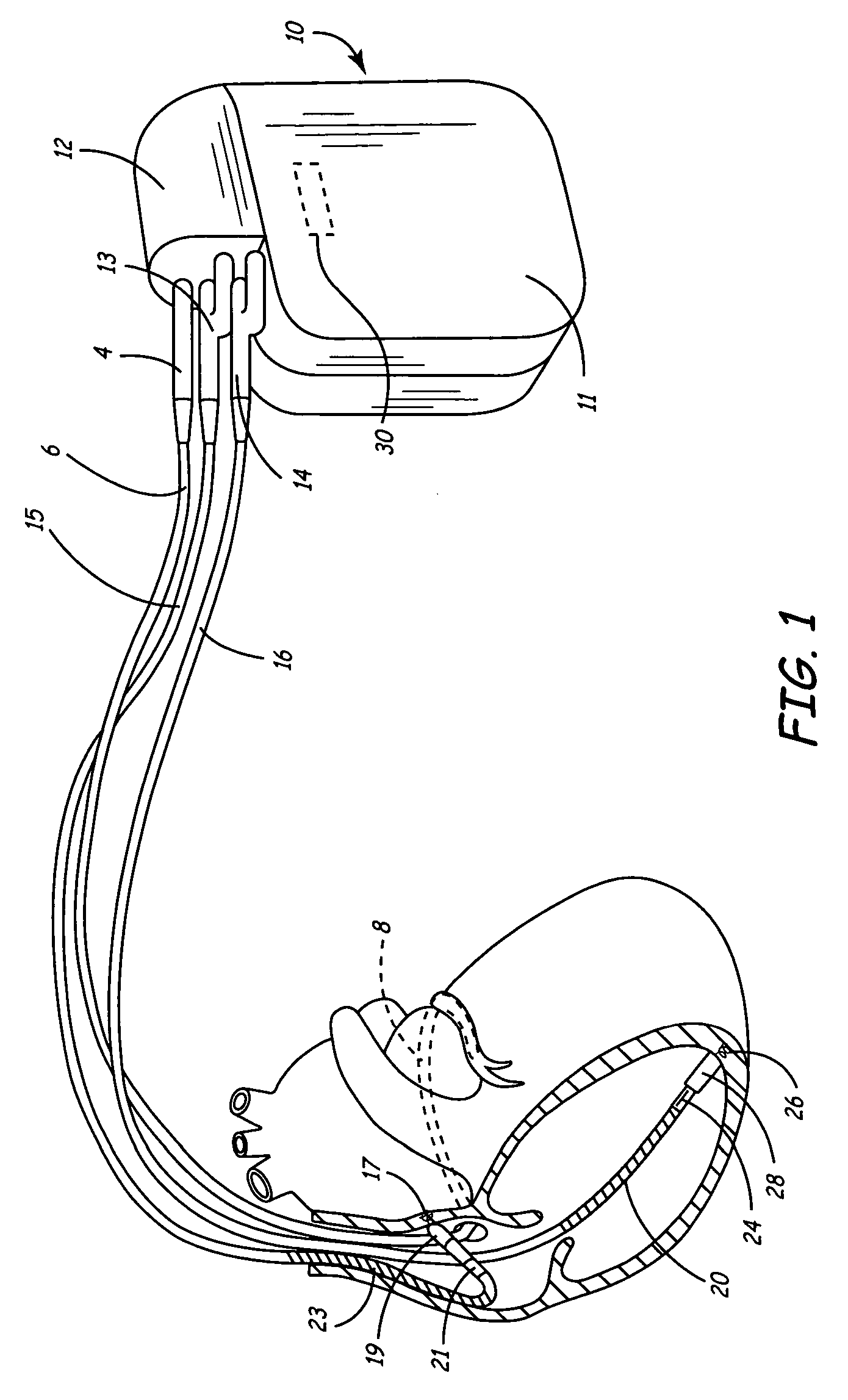
[0023]FIG. 1 is a schematic diagram of a pacemaker / cardioverter / defibrillator and lead set of a type in which the present invention may usefully be practiced. The ventricular lead includes an elongated insulative lead body 16, carrying three mutually insulated conductors. Located adjacent the distal end of the lead are a ring electrode 24, an extendable helix electrode 26, mounted retractably within an insulative electrode head 28, and an elongated coil electrode 20. Each of the electrodes is coupled to one of the conductors within the lead body 16. Electrodes 24 and 26 are employed for cardiac pacing and for sensing ventricular depolarizations. At the proximal end of the lead is a bifurcated connector 14, which carries three electrical connectors, each coupled to one of the coiled conductors.

[0024]The atrial / SVC lead includes an elongated insulative lead body 15, also carrying three mutually insulated conductors. Located adjacent the J-shaped distal end of the lead are a ring elect...


PUM


Abstract

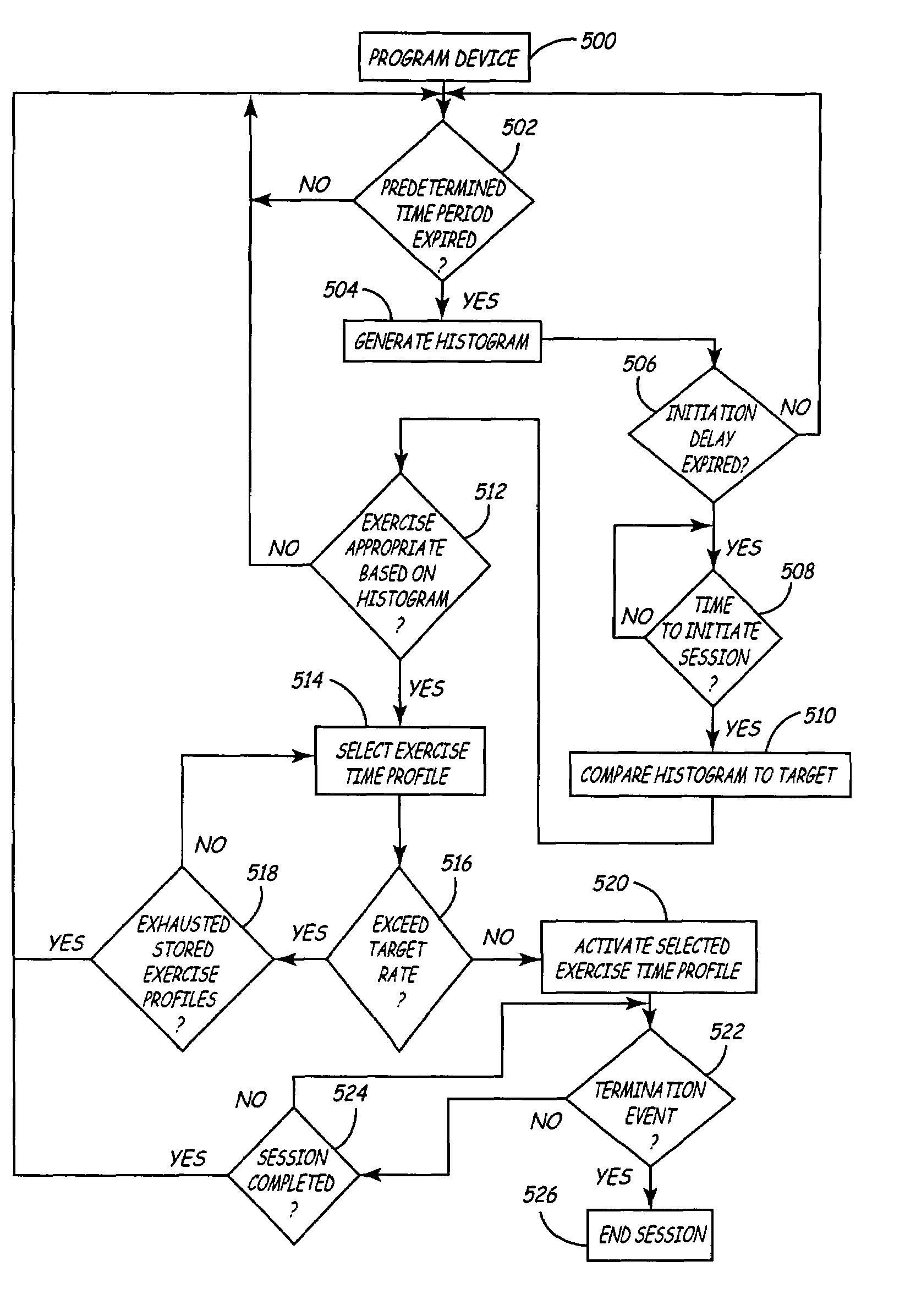
A method and apparatus for varying a parameter in an implantable medical device that includes a plurality of electrodes stimulating heart tissue and sensing cardiac signals, a timing and control device controlling the stimulation of heart tissue by the plurality of electrodes and measuring intervals between the sensed cardiac signals, a storage device storing the measured intervals, and a microprocessor. The microprocessor determines heart rate variability in response to the stored intervals, compares the determined heart rate variability to a predetermined target rate profile, adjusts the parameter from a first setting to a second setting different from the first setting in response to the comparing of the determined heart rate variability and the predetermined target rate profile, and adjusts the parameter from the second setting to a termination setting in response to a termination event or expiration of a first predetermined time period.

Description

FIELD OF THE INVENTION[0001]The present invention relates generally to implantable medical devices, and in particular, the present invention relates to an implantable medical device that provides variations of a baseline heart rate to reflect activities of daily living and circadian variation in patients who are sedentary to improve the strength and functioning of the heart.BACKGROUND OF THE INVENTION[0002]Several advances in pacing have occurred over the years by providing improved methods in sensing natural pacing rhythms. For instance, in demand pacing devices, the objective is to provide stimulatory pulses in the absence of the natural heartbeat. That is, the pacemaker or pacemaker / cardioverter / defibrillator is designed to deliver a pulse at a fixed rate as long as no natural heartbeat is sensed. Sensing of the natural frequency of heartbeats can be done to accommodate changes in the natural pacing frequency such as during natural rhythms of sleep or exercise.[0003]Benefits have...

Claims


Application Information

Patent Timeline
Patent Type & Authority Patents(United States)
IPC IPC(8): A61N1/362A61N1/365
CPCA61N1/365A61N1/36592
Inventor BAKKEN, EARL E.BERGMAN, REBECCA M.COMBS, WILLIAM J.MARKOWITZ, H. TOBY
Owner MEDTRONIC INC
Learn More