Window pane and a method of bonding a connector to the window pane

a technology of window panes and connectors, which is applied in the direction of coupling device connections, conductive pattern formation, transportation and packaging, etc., can solve the problems of connectors detaching from glass windows, undesirable lead soldering, and solder cracks in prior art, so as to avoid deficiencies and eliminate lead use

Inactive Publication Date: 2006-11-14
AGC AUTOMOTIVE AMERICAS
View PDF49 Cites 48 Cited by
  • Summary
  • Abstract
  • Description
  • Claims
  • Application Information

AI Technical Summary

Benefits of technology

[0009]The subject invention includes a method of bonding an electrical connector to an electrical conductor with the connector and conductor each having predefined melting points. The method comprises the step providing a glass substrate. The electrical conductor is deposited over a portion of the glass substrate. The connector is placed over the conductor. The connector is oscillated relative to the conductor to bond the connector to the conductor while maintaining the temperatures of the connector and conductor below the predefined melting points and without damaging the glass substrate.
[0011]Accordingly, the subject invention sets forth a method of bonding a connector to a conductor that eliminates the use of lead and avoids the deficiencies of the prior art methods. Further, the subject invention includes a unique foil disposed between the connector and conductor to overcome additional deficiencies in the prior art.

Problems solved by technology

Although often effective, the prior art lead soldering is undesirable as lead is considered an environmental contaminant.
The lead solder can also crack, which causes the connector to detach from the glass window.
Further, the heating involved can cause cracking in the glass substrate.
Although avoiding the issues with lead soldering, the friction welding technique of the '446 patent has a number of deficiencies.
First, this rotating technique requires that the connector be symmetrical, which greatly reduces the design options for the connectors.
Also, the melting of the connector and conductor is an undesirable affect in that the conductor can be completely removed from the glass substrate thereby creating a disconnect between the connector and conductor.
Further, the rapid rotation and / or pressure can create undesirable mechanical and thermal shocks that could fracture the glass substrate.

Method used


Image

  • Window pane and a method of bonding a connector to the window pane
  • Window pane and a method of bonding a connector to the window pane
  • Window pane and a method of bonding a connector to the window pane

Examples


Embodiment Construction

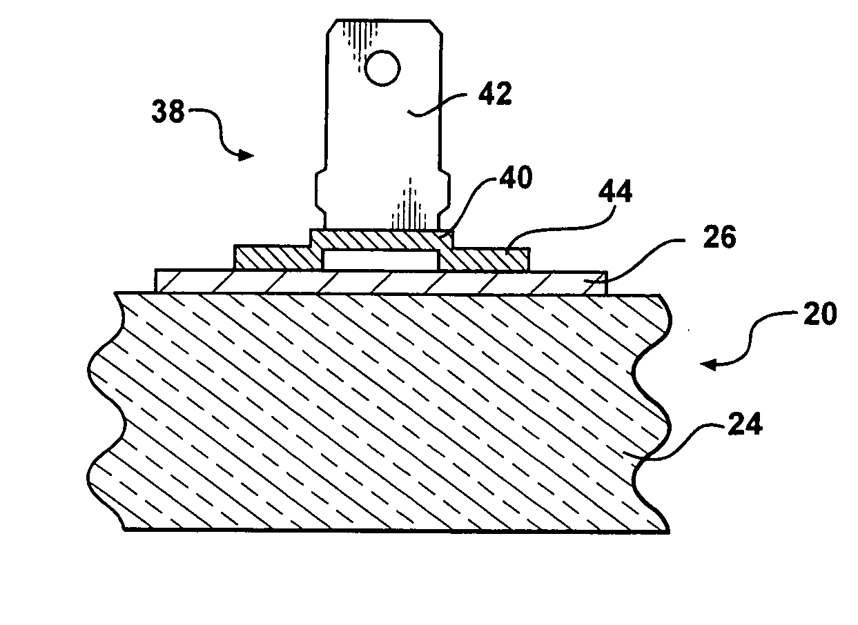
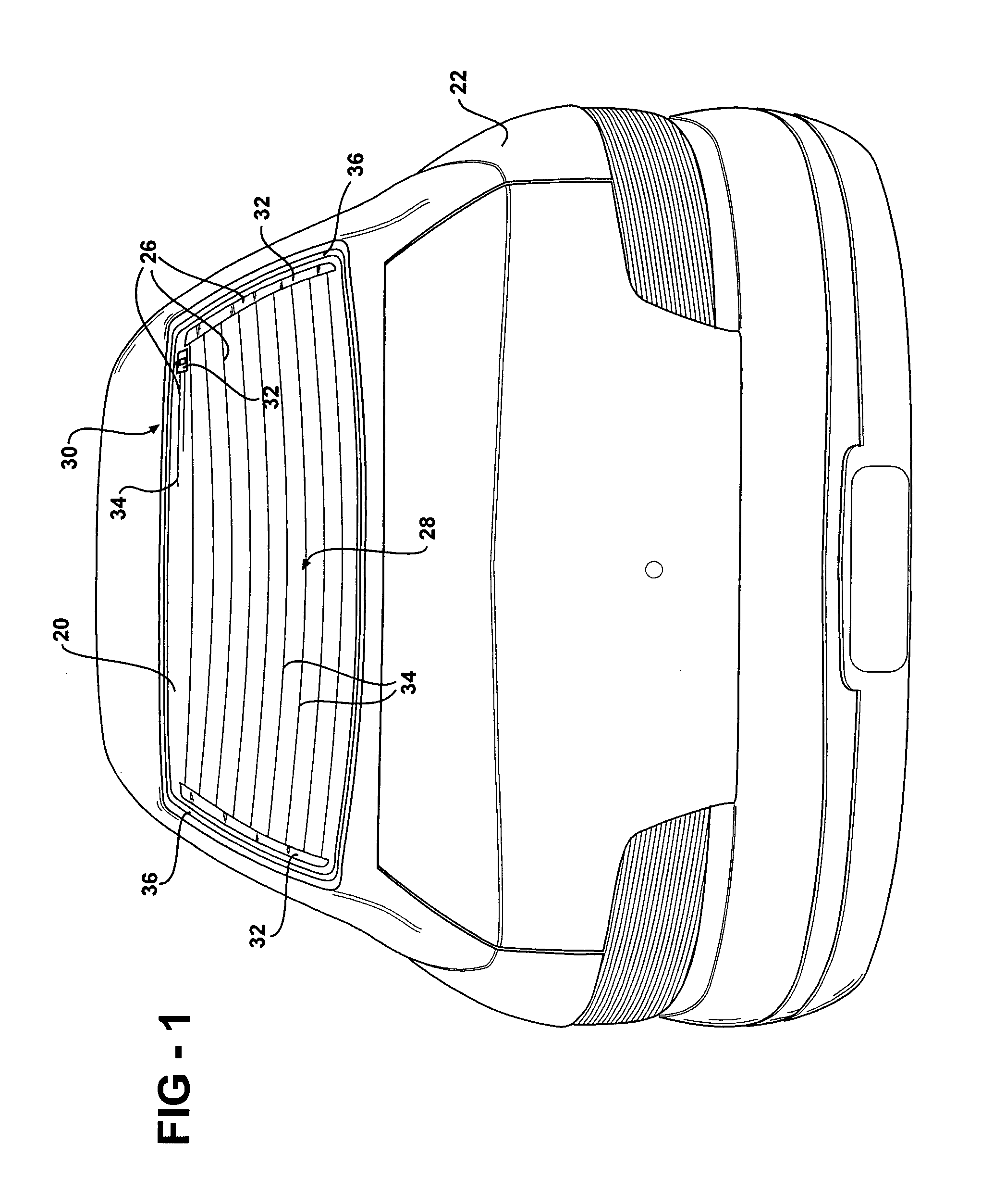
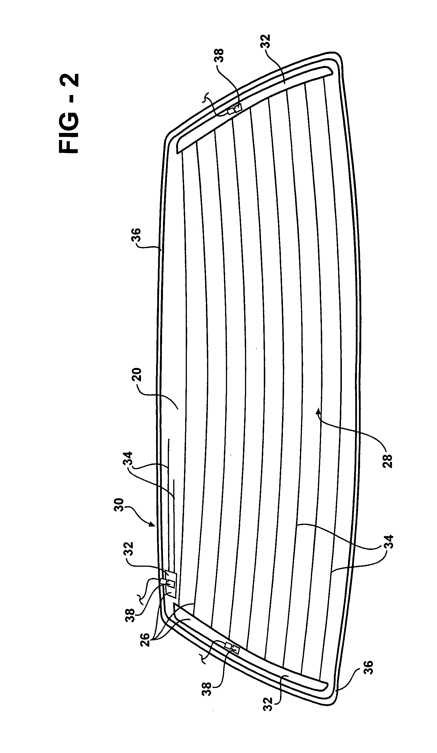
[0027]Referring to the Figures, wherein like numerals indicate like or corresponding parts throughout the several views, a window pane 20 for a vehicle 22 is generally shown in FIGS. 1 and 2. The window pane 20 illustrated is a backlite (rear window) of the vehicle 22. As will become apparent, the subject invention can be equally incorporated into a windshield, side window, or any other window pane 20 in the vehicle 22. Referring also to FIGS. 3–5, the window pane 20 includes a substrate 24 formed from glass of any suitable composition. Preferably, the glass substrate 24 is further defined as an automotive glass. Even move preferably, the automotive glass is further defined as a soda-lime-silica glass.

[0028]As shown in FIGS. 1–5, the window pane 20 also includes an electrical conductor 26 coupled to the glass substrate 24. The electrical conductor 26 may be formed of any suitable material. Preferably, the electrical conductor 26 is formed of a silver paste and the silver paste is bo...


PUM

PropertyMeasurementUnit
temperatureaaaaaaaaaa
frequencyaaaaaaaaaa
frequencyaaaaaaaaaa

Abstract

A method of bonding a connector to an electrical conductor. The conductor is applied to a glass substrate and the connector is placed over the conductor. An ultrasonic welding apparatus is used to oscillate the connector relative to the conductor to bond the connector to the conductor while maintaining the temperatures of the connector and conductor below the predefined melting points and without damaging the glass substrate. In addition, an electrically conductive foil can be disposed between the connector and the conductor for ensuring electrical communication between the connector and the conductor.

Description

BACKGROUND OF THE INVENTION[0001]1. Field of the Invention[0002]The subject invention relates to window panes for vehicles and a method of bonding an electrical connector to an electrical conductor applied to the window pane.[0003]2. Description of Related Art[0004]Glass window panes for vehicles, such as windshields, backlites (rear windows), and side windows, frequently include electrical conductors applied to a glass substrate of the window pane. The electrical conductors are typically formed of a silver paste and include one or more pads with a number of leads extending from the pad. The electrical conductors can serve a number of purposes, such as heaters, radio or cellular phone antennas, or keyless entry circuits.[0005]A connector is bonded to the pad to provide electrical communication between a device, such as a heater controller, radio, cell phone, etc., and the electrical conductors. The connector is adapted to receive an end of a wiring harness from the heater controller...

Claims


Application Information

Patent Timeline
Patent Type & Authority Patents(United States)
IPC IPC(8): H01R43/00
CPCH01R43/0207H01R43/0242H01R43/0263H01R13/03Y10T29/49117Y10T29/49174Y10T29/49155Y10T29/49147H01R2201/26
Inventor ACKERMAN, MARK S.HOEPFNER, TIMOTHY P.
Owner AGC AUTOMOTIVE AMERICAS
Why Eureka
Try Eureka