Illuminated ruler

Inactive Publication Date: 2006-11-14
MANNING STEPHEN R
View PDF15 Cites 14 Cited by
  • Summary
  • Abstract
  • Description
  • Claims
  • Application Information

AI Technical Summary

Benefits of technology

[0003]In light of the problems associated with measuring fish in darkened environments, it is a principal object of the invention to provide a ruler whose ruled markings are brightly

Problems solved by technology

Measuring a fish caught at night from a small boat has never been easy.
The fish itself is slippery and mobile, often requiring two hands to hold.
Under such circumstances, it can be nearly impossible to steady a flashlight or lamp adjacent a ruler to g

Method used


Image

  • Illuminated ruler
  • Illuminated ruler

Examples


Embodiment Construction

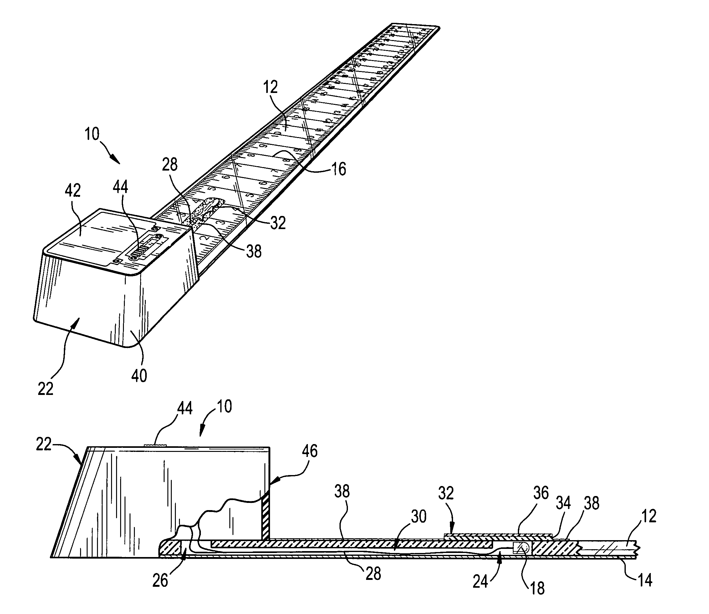
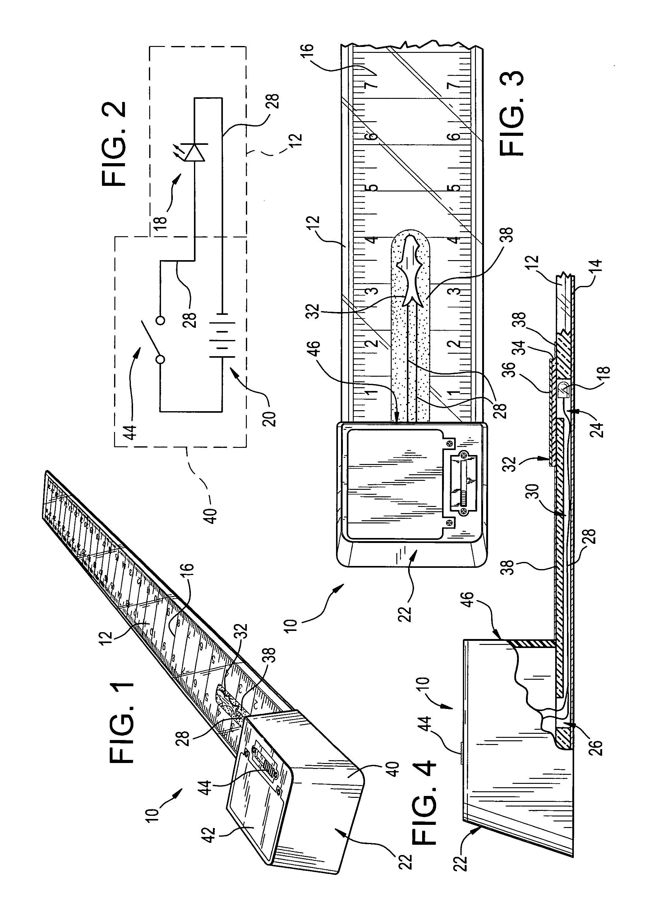
[0016]Referring now to the FIGS., an illuminated ruler in accordance with the present invention is shown at 10. Ruler 10 includes a light transmissive bar 12 whose bottom is covered by an opaque film 14 bearing printed indicia in the form of ruled markings 16. A light-emitting diode (LED) 18 is embedded within bar 12 for illuminating ruled markings 16 in the dark. LED 18 is selectively energized by a battery 20 carried in a control pack 22 affixed to one end of bar 12.

[0017]Bar 12 is formed of a transparent plastic material that is stiff and scratch-resistant. As shown, bar 12 is about 22 inches (56 cm) in length, 3 inches (7.6 cm) in width, and 0.25 inches (0.64 cm) in thickness to be suitable for use in measuring freshwater game fish. Nonetheless, these dimensions are a matter of design choice and can be enlarged or reduced as a user may desire.

[0018]Film 14 is formed of an opaque plastic material and is affixed by means of a suitable adhesive to the bottom of bar 12. Ruled markin...


PUM


Abstract

An illuminated ruler including a light transmissive bar having opposed ends. An opaque film bearing printed indicia in the form of ruled markings is affixed to the bottom of the light transmissive bar. A light-emitting diode is embedded within the light transmissive bar for illuminating the ruled markings. A battery is carried atop one end of the bar and is connected to the light-emitting diode for energizing and illuminating the light-emitting diode.

Description

FIELD OF THE INVENTION[0001]The present invention relates generally to geometrical instruments and, more particularly, to anatomical gauges.BACKGROUND OF THE INVENTION[0002]Measuring a fish caught at night from a small boat has never been easy. The fish itself is slippery and mobile, often requiring two hands to hold. The boat may also be moving, pitching and rolling with the surf. Under such circumstances, it can be nearly impossible to steady a flashlight or lamp adjacent a ruler to get an accurate measurement of the length of the fish. Deciding whether to keep or release a fish caught under such conditions can be a matter of guesswork. Of course, keeping an undersized fish is something that a fisherman does at his own peril, risking: the loss of his fishing license, the confiscation of his fishing gear, and, perhaps, a large fine.SUMMARY OF THE INVENTION[0003]In light of the problems associated with measuring fish in darkened environments, it is a principal object of the inventio...

Claims


Application Information

Patent Timeline
IPC IPC(8): B43L7/00F21V33/00
CPCB43L7/00G01B3/04
Inventor MANNING, STEPHEN R.
Owner MANNING STEPHEN R
Why Eureka
Try Eureka