Musical baby bottle

Inactive Publication Date: 2006-11-14
CARRASCO RAYMOND +1
View PDF10 Cites 16 Cited by
  • Summary
  • Abstract
  • Description
  • Claims
  • Application Information

AI Technical Summary

Benefits of technology

[0009]The present invention provides a baby bottle with music playing capabilities in which the music player may be actuated by omnidirectional tilting of the bottle. Furthermore, the present invention involves a novel system of actuation by tilting the bottle that totally avoids the use of any hazardous substance.
[0011]Unlike other infant feeding container systems that play music, the musical baby bottle of the present invention has a cavity in the base with a sloped floor leading to a detent recess, which may be a dimple at the axial center of the base. A small, relatively heavy sphere such as a ball bearing or marble is located in the cavity. The floor of the cavity is inclined from the periphery of the cavity away from the bottom of the liquid container and toward the axial center of the base where the detent is located. The sloped incline of the cavity floor should not be so shallow that the sphere will roll out of the detent due to a slight agitation of the liquid container. On the other hand, inclination should not be so steep that the sphere will remain lodged in the detent unless the liquid container is tilted so far that the closed bottom of the container is above its top. Preferably, the floor of the cavity is inclined an angle of at least two degrees but no greater than ten degrees to allow the sphere to roll back easily into the detent when the liquid container is placed in an upright, vertical orientation.

Problems solved by technology

While the switches are alternatively closed by tilting the bottle in certain directions, this system does not provide for omnidirectional operation.
Furthermore, this system carries with it the risk of exposure to mercury, which represents a serious hazzard to the health of the infant and others.

Method used


Image

  • Musical baby bottle
  • Musical baby bottle
  • Musical baby bottle

Examples


Embodiment Construction

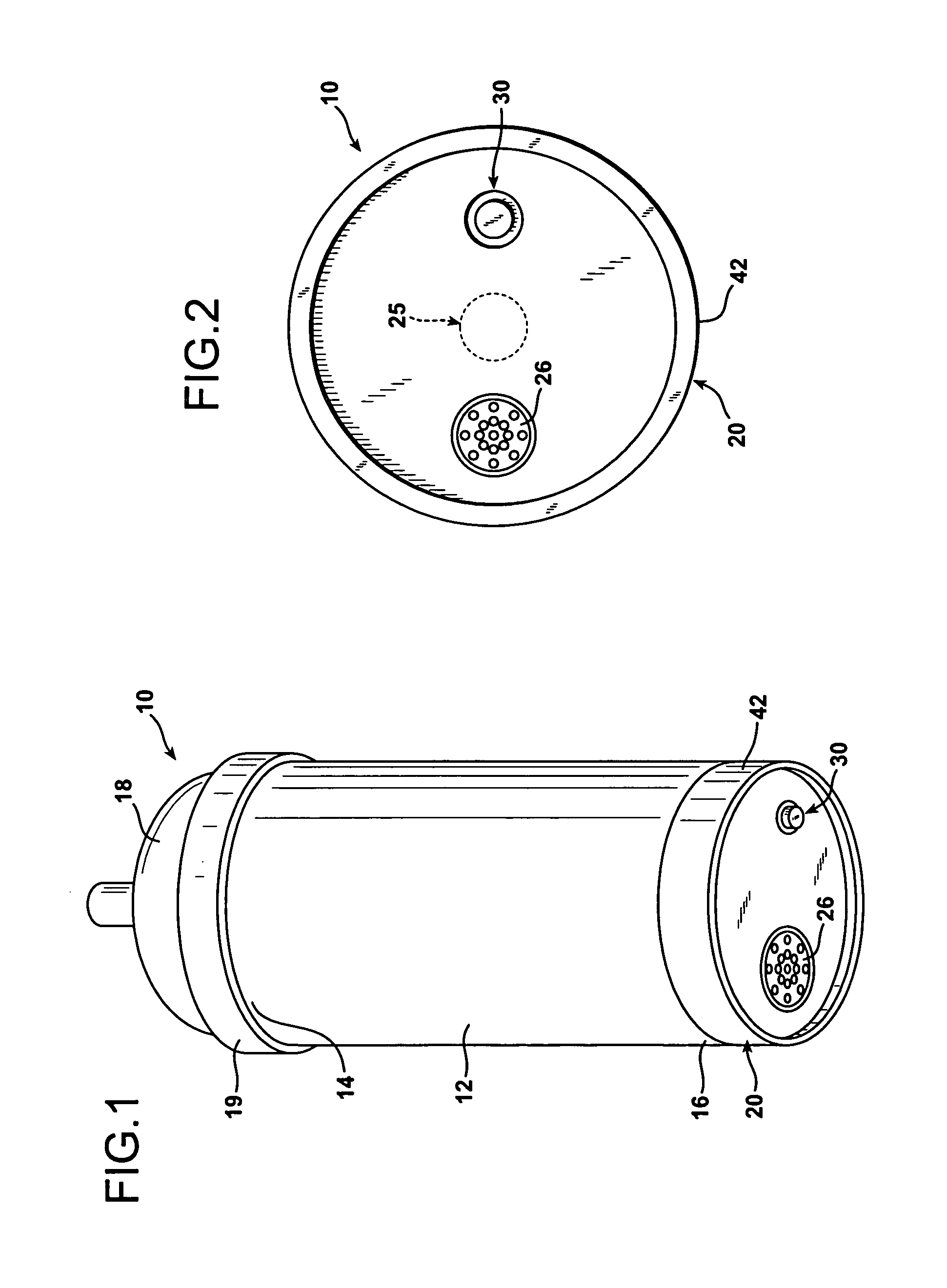
[0029]FIG. 1 illustrates a musical baby bottle indicated generally at 10 comprising an elongated, generally cylindrical container 12 having an open top end 14 and a closed bottom end 16. The open top end 14 has a conventional baby feeding nipple 18 releaseably secured thereto by an annular, plastic collar 19.

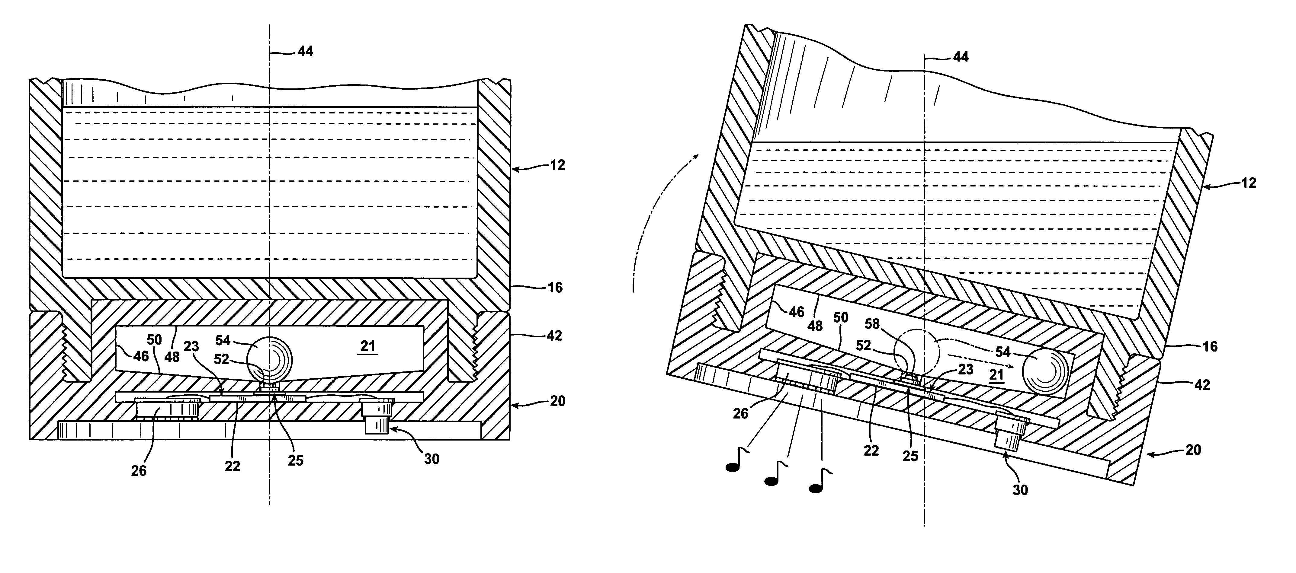
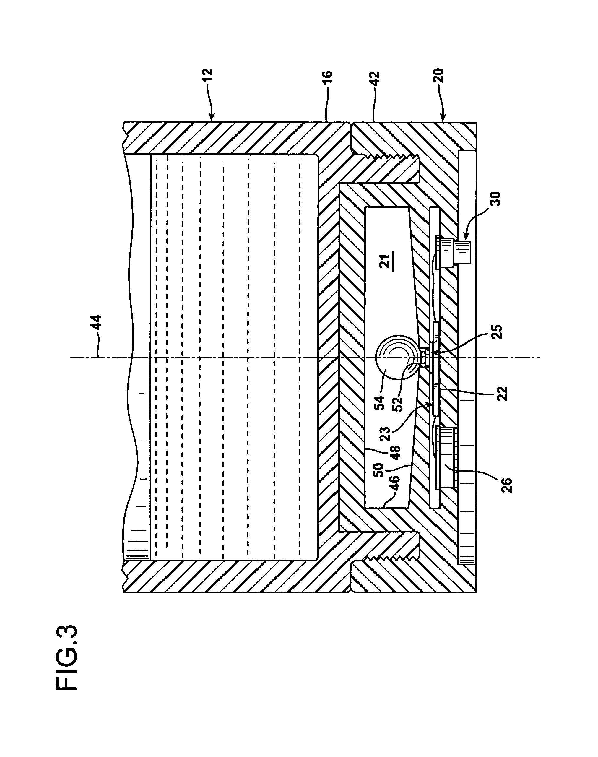
[0030]The musical baby bottle 10 also includes a hollow, generally disk-shaped base 20 that defines within its structure an enclosed cavity 21, as indicated in FIGS. 3 and 4. Beneath the cavity 21 there is a musical player 23 that includes a digital, preprogrammed electronic chip 22 with an electrical output to an audio speaker 26. The musical player 23 is powered by a small battery 24 disposed within the base 20. The battery 24 provides power to the music player 23 through a depressible, gravity-operated, dynamic switching mechanism including a dynamic electrical switch 25 having a switch actuator with a switch contact 41.

[0031]The base 20 is preferably formed of rubber or plas...


PUM


Abstract

A musical baby bottle is provided with an omnidirectional, gravity-operated switching mechanism for turning a musical player on and off, depending upon the orientation of the bottle. The infant nursing bottle of the invention employs a liquid container and a base containing the electrical switching mechanism releaseably attached to the bottom of the liquid container, such as by a threaded connection. A hollow cavity is defined within the structure of the base. The cavity has an inclined floor that slopes from the periphery of the cavity toward the axial center of the base. A detent recess is located at the axial center of the base and an electrical switch having a switch actuator is located at the detent. A sphere within the cavity rolls by gravity across the inclined surface of the cavity floor. The sphere lodges in the detent when the base and liquid container supported upon the base are oriented vertically upright, as when placed upon a horizontal surface. When the base and liquid container are tilted, as when feeding a baby the sphere dislodges from the detent thereby closing a circuit from a battery to the music player to play a lullaby or other calming music.

Description

BACKGROUND OF THE INVENTION[0001]1. Field of the Invention[0002]The present invention relates to a baby bottle containing a music player that is operated by omnidirectional tilting of the bottle from vertical alignment.[0003]2. Description of the Prior Art[0004]Baby bottles have been in continuous use for many, many years for nursing and feeding liquids to infant children. Conventional baby bottles are formed as elongated, tubular containers of glass or plastic having a closed bottom end and an open mouth at the opposite, top end. Rubber nipples are releaseably secured to the open, top ends of conventional bottles by means of annular plastic collars which provide a liquid-tight seal at the mouth of the bottle. Conventional infant feeding bottles of this type may be cylindrical in cross-sectional shape, but are sometimes formed with a polygonal outer cross-sectional configuration.[0005]Infant children are often quite temperamental during feeding. The distress of many infants during f...

Claims


Application Information

Patent Timeline
IPC IPC(8): A63H33/00A47D15/00
CPCA61J9/00A61J2017/002
Inventor CARRASCO, RAYMONDCARRASCO, MARIA
Owner CARRASCO RAYMOND
Why Eureka
Try Eureka