Rotary massaging stick

a rotary and massage technology, applied in massage, non-surgical orthopedic devices, physical therapy, etc., can solve the problem that the attractiveness of the sexual toy of this design is less for consumers

Inactive Publication Date: 2006-11-14
HSU YU
View PDF3 Cites 1 Cited by
  • Summary
  • Abstract
  • Description
  • Claims
  • Application Information

AI Technical Summary

Benefits of technology

[0005]The present invention has been accomplished under the circumstances in view. It is the main object of the present invention to provide a rotary massaging stick, which drives rotary massaging ball assemblies to rotate in reversed directions to stimulate the G point in the vagina of a woman, causing the woman to reach the climate of sexual excitement.

Problems solved by technology

However, a sex toy of this design is less attractive to consumers because the rotary massaging ball assemblies can be rotated in one specific direction only.

Method used


Image

  • Rotary massaging stick
  • Rotary massaging stick
  • Rotary massaging stick

Examples


Embodiment Construction

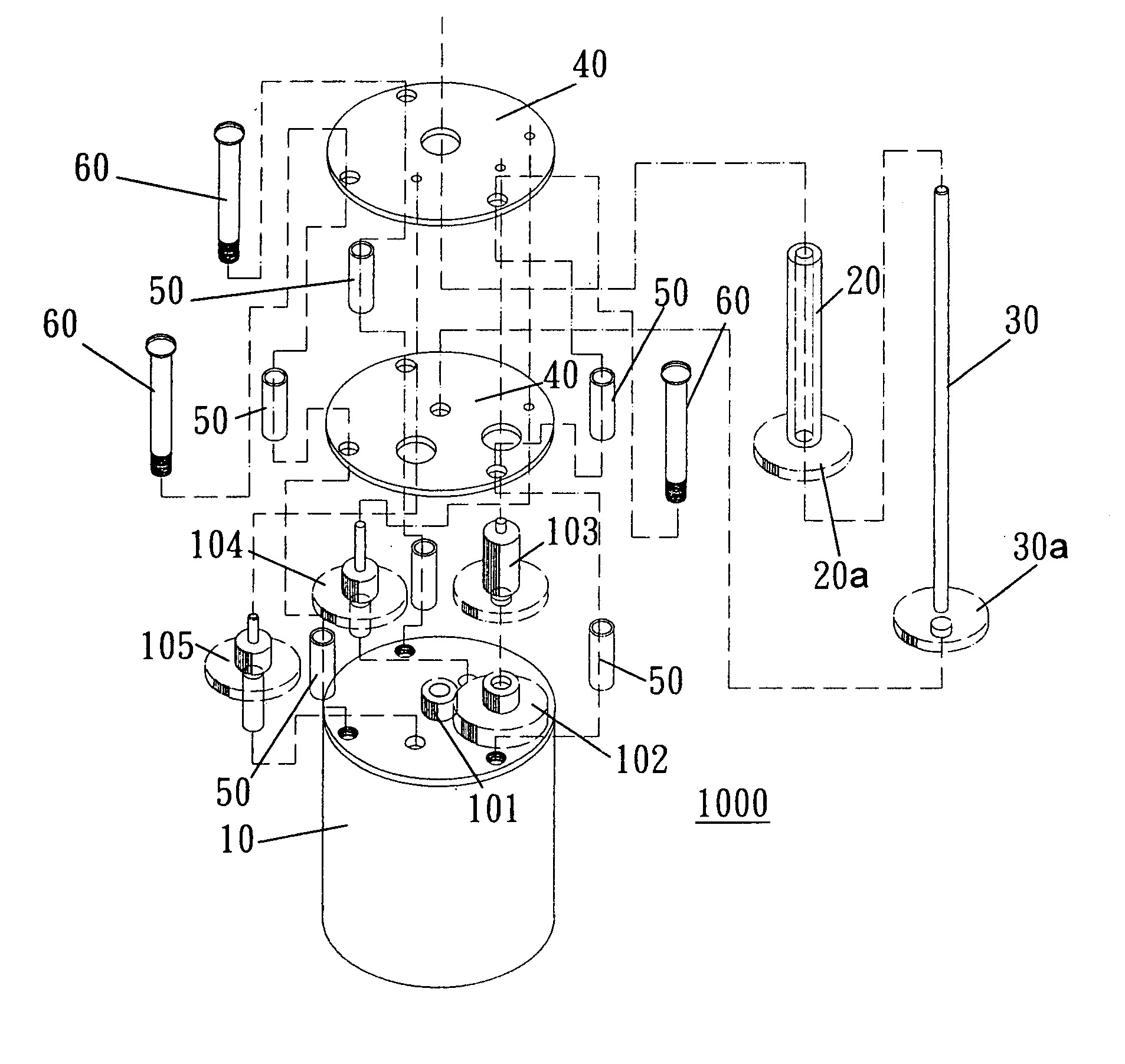
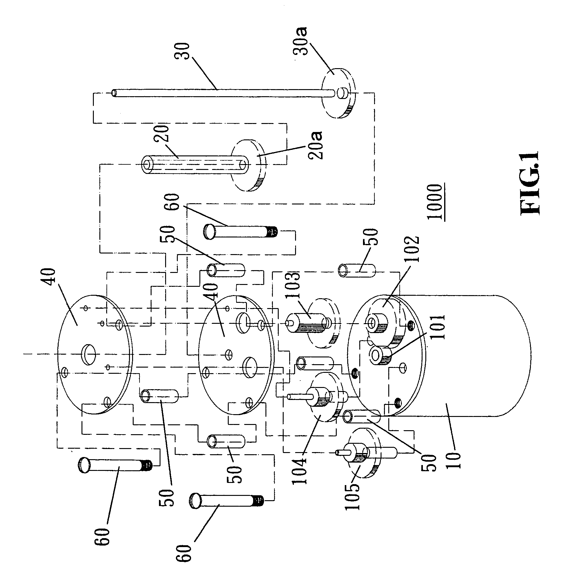
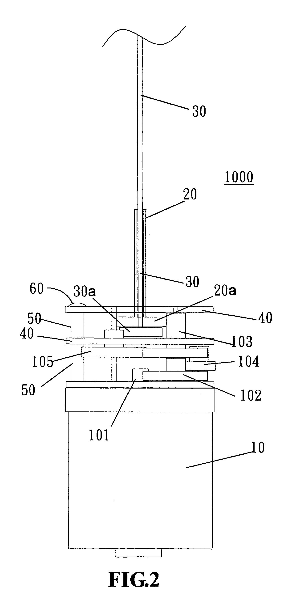
[0015]Referring to FIGS. 1˜3, a rotary massaging stick is shown comprising a transmission mechanism 1000. The transmission mechanism 1000 comprises a motor 10, a plurality of circular mounting plates 40 fastened to the housing of the motor 10 at different elevations with spacer tubes 50 and screw bolts 60, a stepped gear A 102 meshed with the pinion 101 at the output shaft of the motor 10, a stepped gear B 103 fixedly connected in parallel to the stepped gear A 102, a stepped gear C 104 meshed with the stepped gear A 102 and the stepped gear B 103, a sleeve 20 rotatably mounted in one circular mounting plate 40 at the center, a first transmission gear 20a fixedly mounted on the sleeve 20 and meshed with the stepped gear B 103, a transmission shaft 30 inserted through the sleeve 20, a second transmission gear 30a fixedly mounted on the bottom end of the transmission shaft 30, and a stepped gear D 105 meshed between the second transmission gear 30a and the stepped gear B 103. Massagin...


PUM


Abstract

A rotary massaging stick having rotary massaging ball assemblies rotatable in reversed directions by a motor through a transmission gear train for stimulating the G point in the vagina of a woman to cause the woman to reach the climate of sexual excitement.

Description

BACKGROUND OF THE INVENTION[0001]1. Field of the Invention[0002]The present invention relates generally to a rotary massaging stick and more particularly, to such a rotary massaging stick, which is practical for simulating the G point in the vagina of a woman to reach the climate of sexual excitement.[0003]2. Description of the Related Art[0004]Various sex toys have been disclosed for helping people to reach the climate of sexual excitement, and have appeared on the market. A conventional rotary massaging stick for this purpose has rotary massaging ball assemblies that can be rotated in one specific direction to stimulate the vagina. However, a sex toy of this design is less attractive to consumers because the rotary massaging ball assemblies can be rotated in one specific direction only.SUMMARY OF THE INVENTION[0005]The present invention has been accomplished under the circumstances in view. It is the main object of the present invention to provide a rotary massaging stick, which d...

Claims


Application Information

Patent Timeline
Patent Type & Authority Patents(United States)
IPC IPC(8): A61H15/00A61H19/00A61H21/00
CPCA61H15/0085A61H19/44A61H21/00A61H2015/0042A61H2015/005A61H2201/1671A61H19/00
Inventor HSU, YU
Owner HSU YU
Why Eureka
Try Eureka