System and method for estimating the azimuth pointing angle of a moving monopulse antenna

a monopulse antenna and azimuth pointing angle technology, applied in the direction of antennas, instruments, antenna details, etc., can solve the problems of limiting the accuracy with which the absolute position of the moving target can be established, cumbersome operation to perform, and large errors in the monopulse measurement, so as to achieve the effect of increasing the accuracy of tracking purposes

Active Publication Date: 2006-11-14
THE BOEING CO
View PDF11 Cites 7 Cited by
  • Summary
  • Abstract
  • Description
  • Claims
  • Application Information

AI Technical Summary

Problems solved by technology

To get absolute positional information regarding the monopulse null angle, the angle between the antenna boresight 118 and the star tracker housing must be determined with extreme accuracy, which is a very cumbersome operation to perform.
Moreover, small inaccuracies in the monopulse null angle can introduce large errors in the monopulse measurement angle of a moving target relative to the boresight 118, particularly for spaceborne radar systems.
These errors limit the accuracy with which the absolute position of the moving target can be established.
As a result, the usefulness of spaceborne radar systems designed to detect and locate moving targets is limited.

Method used


Image

  • System and method for estimating the azimuth pointing angle of a moving monopulse antenna
  • System and method for estimating the azimuth pointing angle of a moving monopulse antenna
  • System and method for estimating the azimuth pointing angle of a moving monopulse antenna

Examples


Embodiment Construction

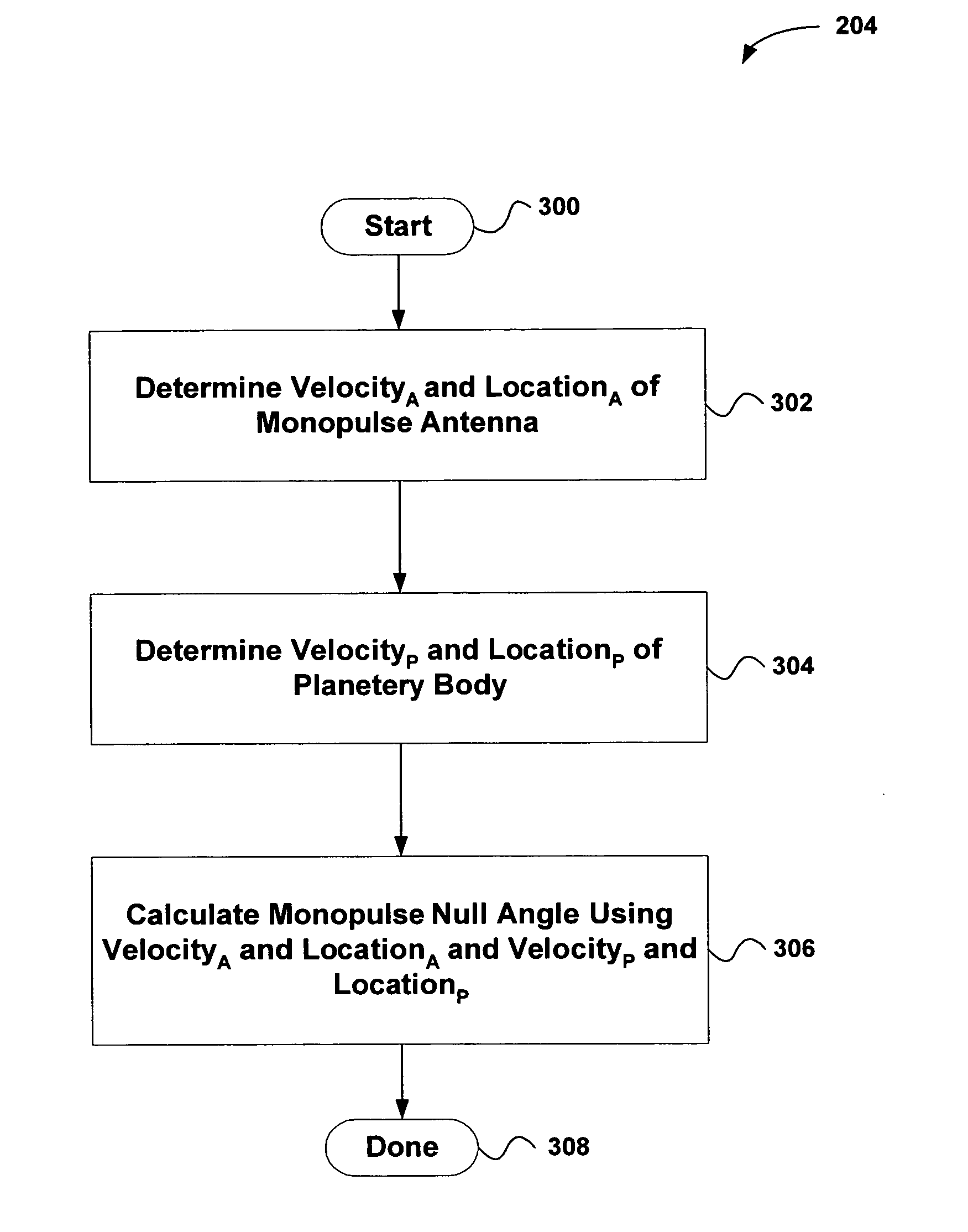
[0024]An invention is disclosed for determining the azimuth pointing angle of a monopulse antenna. In general, embodiments of the present invention determine the monopulse null angle of a monopulse antenna by obtaining a ground signature, which is utilized to deduce very accurately where the antenna is pointing. In this manner, the monopulse antenna azimuth pointing angle can be determined regardless of antenna misalignments or instabilities.

[0025]In the following description, numerous specific details are set forth in order to provide a thorough understanding of the present invention. It will be apparent, however, to one skilled in the art that the present invention may be practiced without some or all of these specific details. In other instances, well known process steps have not been described in detail in order not to unnecessarily obscure the present invention.

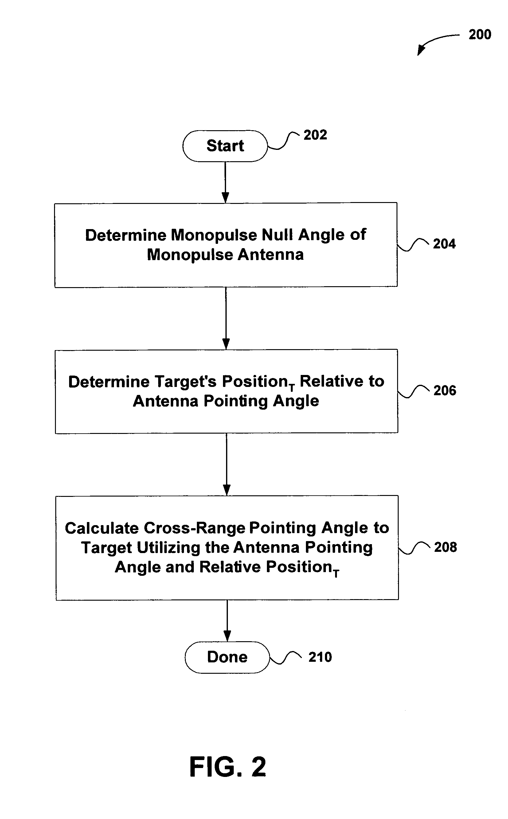
[0026]FIG. 2 is a flowchart showing a method 200 for determining the cross-range azimuth pointing angle to a target, i...


PUM


Abstract

An invention is provided for determining the azimuth pointing angle of a moving monopulse antenna. Pulses of energy are broadcast at the surface of a planetary body. Reflected signals are received from the surface of the planetary body using a plurality of feeds. A monopulse ratio is then calculated based on a sum pattern and a difference pattern. The sum pattern is based on the sum of the reflected signals received using the feeds, and the difference pattern is based on a difference of the reflected signals received using the feeds. An azimuth pointing angle of a monopulse antenna is then calculated using the monopulse ratio.

Description

BACKGROUND OF THE INVENTION[0001]1. Field of the Invention[0002]This invention relates generally to tracking devices, and more particularly to estimating the azimuth pointing angle of a monopulse antenna.[0003]2. Description of the Related Art[0004]Currently, monopulse detection systems are widely utilized in airborne and spaceborne radar systems to locate moving targets. A monopulse detection system detects an azimuth angle to a target and thereafter locates the absolute position of the target based on the monopulse antenna azimuth and elevation azimuth pointing angles and the relative azimuth angle to the target. In particular, a signal is radiated from a transmitting antenna and reflected off the target. The reflected signal then is received at the monopulse detection system through two or more receiving feeds. Utilizing the phase between the signals received at the individual feeds, data regarding the azimuth angle of the target to the detection system is determined, as illustra...

Claims


Application Information

Patent Timeline
Patent Type & Authority Patents(United States)
IPC IPC(8): G01S13/00
CPCG01S13/4418H01Q1/125H01Q1/1257
Inventor MCCORD, HENRYSCHWEITZER, BERNARDJENSEN, ERIC B.HALLMAN, STEVE A.
Owner THE BOEING CO
Why Eureka
Try Eureka