Adaptive discovery and correction of phase alignment errors in monopulse antenna systems

a monopulse antenna and phase alignment technology, applied in the direction of reradiation, measurement devices, instruments, etc., can solve the problems of increasing the risk of dropping the link, the incorrect assumption of the antenna being pointing directly, and the laborious process

Active Publication Date: 2020-05-28
L3 TECH INC
View PDF0 Cites 2 Cited by
  • Summary
  • Abstract
  • Description
  • Claims
  • Application Information

AI Technical Summary

Problems solved by technology

However, if the object is within a sidelobe, and if the comparator network detects a sum channel peak or a difference channel null, the antenna will incorrectly assume that it is pointing directly at the object.
Using GPS data in this way also requires that the antenna be physically oriented with respect to true north which can be a tedious process.
This increases the risk of dropping the link due to marginal signal-to-noise ratio performance as the target moves away.
Accordingly, a modem lock is a poor indicator of mainlobe tracking.

Method used


Image

  • Adaptive discovery and correction of phase alignment errors in monopulse antenna systems
  • Adaptive discovery and correction of phase alignment errors in monopulse antenna systems
  • Adaptive discovery and correction of phase alignment errors in monopulse antenna systems

Examples


Embodiment Construction

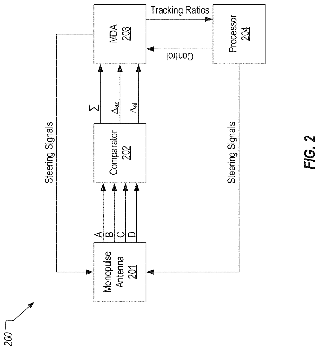
[0023]MDA 203 can be configured to implement the techniques of the present invention to ensure that monopulse antenna 201 is oriented such that the object to be tracked will be positioned within the mainlobe rather than a sidelobe. In other words, MDA 203 can generate steering signals to control the orientation of monopulse antenna 201 in accordance with the techniques of the present invention as will be described below. Monopulse antenna system 200 may also typically include a processor 204 which can interface with MDA 203 to provide control signals to and to receive state and tracking information from MDA 203. Also, processor 204 can be configured to interface with monopulse antenna 201 for the purpose of providing steering signals. Although not shown, monopulse antenna system 200 may include a steering component with which MDA 203 and processor 204 interface for purposes of steering monopulse antenna 201.

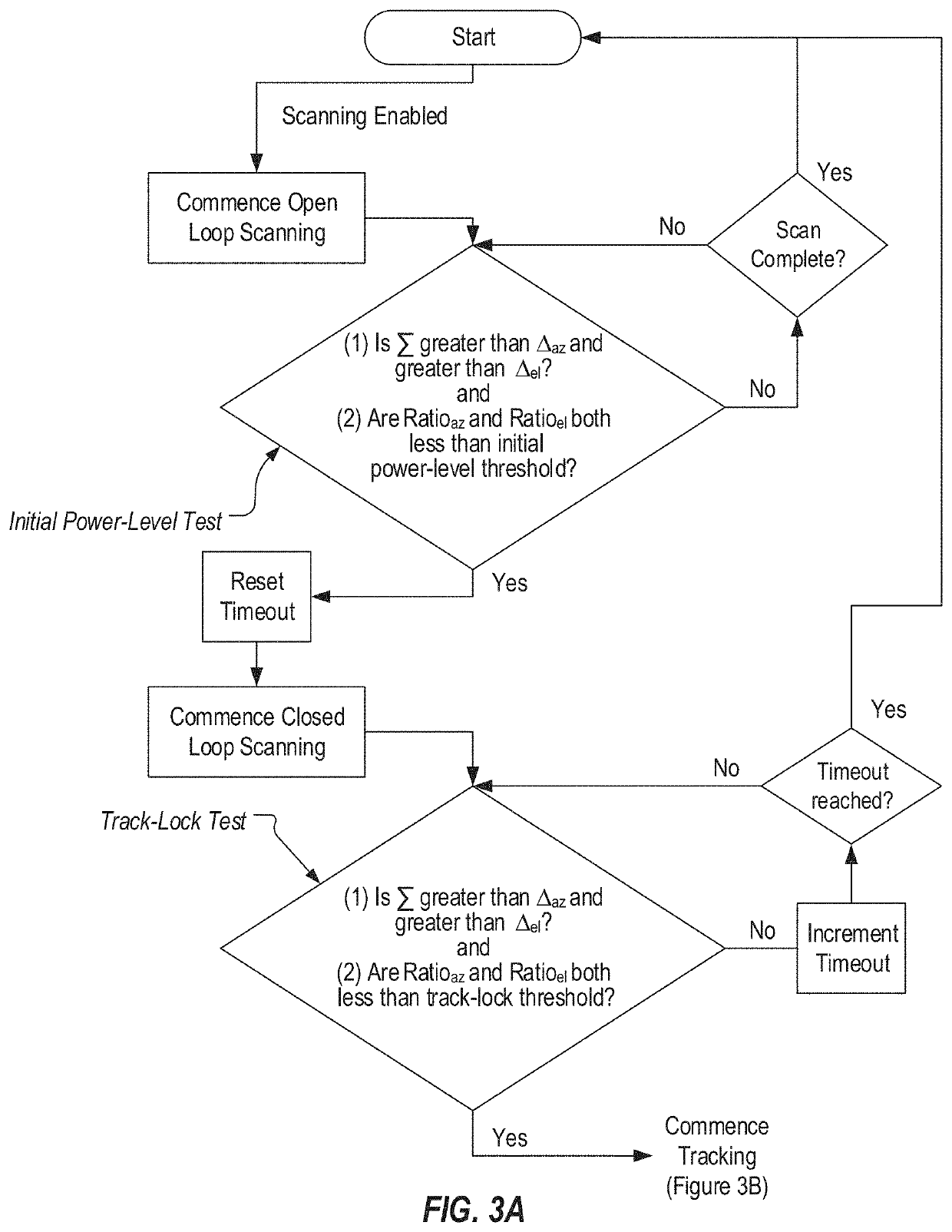
[0024]By way of overview, the present invention utilizes a series of tests d...


PUM


Abstract

A mainlobe detection process can include a number of tests that are performed to define when the monopulse antenna system will transition from open loop scanning to closed loop scanning and then to tracking. A hybrid tracking technique is also provided which adaptively discovers and corrects for phase alignment error. Magnitude-only tracking can be performed initially to locate the nulls in the azimuth and elevation ratios and to identify the magnitudes of these ratios at these nulls. Phase tracking can be then performed. During phase tracking, phase corrections can be repeatedly applied to the azimuth and elevation difference channels to correct any phase error that may exist. During this process, the magnitudes of the ratios can be used to determine how the phase corrections should be adjusted. Once the hybrid tracking process is complete, the monopulse antenna system is properly phase-aligned and phase tracking will be correctly employed.

Description

CROSS-REFERENCE TO RELATED APPLICATIONS[0001]This application is a continuation of U.S. patent application Ser. No. 15 / 420,424 which was filed on Jan. 31, 2017.BACKGROUND[0002]A monopulse antenna system is commonly used to implement radar tracking or to track intentional radiators. As its name implies, a monopulse antenna system employs a single pulse to identify the presence of an object in the field of view. This is possible due to the use of multiple antennas which can detect angle information from the arriving signal.[0003]FIG. 1 illustrates an example block diagram of a typical dual-axis monopulse antenna system. As shown, a dual-axis monopulse antenna system may include four individual antennas (A, B, C, and D) each of which are driven by the same arriving signal. If an object is in the field of view of the monopulse antenna system, each individual antenna will receive the reflected (or transmitted) signal. These received signals (which are referred to as A, B, C, and D respec...

Claims


Application Information

Patent Timeline
Patent Type & Authority Applications(United States)
IPC IPC(8): G01S13/68G01S13/44
CPCG01S13/4454G01S13/68G01S13/4481G01S13/4445
Inventor PRESTWICH, SYBENCH, JEFFREY B.MCNAMEE, RICHARD A.
Owner L3 TECH INC
Why Eureka
Try Eureka