Miniature dual-frequency-band coplanar composite monopulse array antenna

An array antenna and monopulse technology, applied in the field of antenna design, can solve problems such as complex antenna structure, misalignment of probes, and difficult processing, and achieve the effects of reducing sidelobes in the far area, ingenious layout, and ingenious structure

Active Publication Date: 2015-11-18
SHANGHAI RADIO EQUIP RES INST
View PDF3 Cites 3 Cited by
  • Summary
  • Abstract
  • Description
  • Claims
  • Application Information

AI Technical Summary

Problems solved by technology

Another prior art feed adopts the form of a multi-mode horn, and the side lobes are -13dB and -22dB respectively
There is also a prior art feed that uses 5 coplanar C-band horns and 4 S-band horns. The efficiency of the C-band is 50%, but the efficiency of the S-band is only 25%, and the side lobe is only about -15dB.
[0004] At present, the microstrip antenna has a low profile and light weight, but the dual-band microstrip antenna generally adopts a multi-layer structure. Due to the large number of layers, a lamination process is required, which is difficult to process, and there may be misalignment of the probes. Unexpected problems such as uneven glue
The waveguide antenna has high efficiency, mature processing technology, and is easy to achieve low sidelobes, but the dual-band waveguide structure antenna will inevitably have problems such as complex structure and poor quality.

Method used


Image

  • Miniature dual-frequency-band coplanar composite monopulse array antenna
  • Miniature dual-frequency-band coplanar composite monopulse array antenna
  • Miniature dual-frequency-band coplanar composite monopulse array antenna

Examples


Embodiment Construction

[0023] The following combination Figure 1 to Figure 6 , a preferred embodiment of the present invention is described in detail.

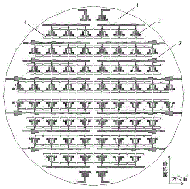
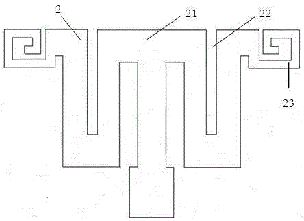
[0024] The miniaturized dual-band coplanar composite monopulse array antenna provided by the present invention includes: a metal reflector 1; a low-frequency radiation front, arranged at the forefront of the monopulse array antenna, such as figure 1 As shown, the low-frequency radiation front includes a plurality of microstrip antenna arrays arranged above the metal reflector 1; the low-frequency elevation plane waveguide power combining network is arranged below the low-frequency radiation front and connected to it; the high-frequency radiation front is arranged below the low-frequency radiation front, and includes a plurality of waveguide antenna line arrays arranged under the metal reflector 1; the high-frequency waveguide power combining network is arranged on It is below and connected to the high-frequency radiation front.

[0025] Such as ...


PUM


Abstract

A miniature dual-frequency-band coplanar composite monopulse array antenna comprises the components of a circular metal reflecting plate which is uniformly divided into four sector-shaped areas; a low-frequency-band radiating array plane which is arranged at the frontmost end of the monopulse array antenna and comprises a plurality of microstrip antenna arrays that are arranged above the metal reflecting plate; a low-frequency-band pitching surface waveguide power synthesizing network which is arranged below the low-frequency-band radiating array plane and is connected with the low-frequency-band radiating array plane; a high-frequency-band radiating array plane which is arranged below the low-frequency-band radiating array plane and comprises a plurality of waveguide opening antenna arrays that are arranged below the metal reflecting plate; and a high-frequency-band waveguide power synthesizing network which is arranged below the high-frequency-band radiating array plane and is connected with the high-frequency-band radiating array plane. The miniature dual-frequency-band coplanar composite monopulse array antenna is advantageous in that relatively low minor lobes and a radiating efficiency which is equivalent with that of a single-frequency single-pulse antenna; furthermore a coupling effect of two frequency bands is reduced; the miniature dual-frequency-band coplanar composite monopulse array antenna has characteristics of small size and double frequencies; ingenious layout is realized and a requirement for combining and being compatible between the antenna arrays in two frequency bands of the space can be satisfied; and furthermore the miniature dual-frequency-band coplanar composite monopulse array antenna has high practicability and wide application prospect.

Description

technical field [0001] The invention relates to an antenna structure, in particular to a miniaturized dual-band coplanar composite monopulse array antenna, which belongs to the field of antenna design. Background technique [0002] At present, multi-band composite guidance has become one of the important development directions of precision guided weapons. Composite guidance radar seeker has the characteristics of active radar seeker and semi-active radar seeker at the same time, learning from each other's strengths and complementing each other's weaknesses, has become one of the hot spots in domestic missile technology research. One of the key technologies of the missile seeker is the design of the dual-band monopulse antenna. [0003] A common dual-band monopulse antenna is a dual-band Cassegrain monopulse antenna, which has a simple structure and is relatively easy to implement, but generally has the problems of low efficiency and high sidelobes. One existing technology ...

Claims


Application Information

Patent Timeline
Patent Type & Authority Applications(China)
IPC IPC(8): H01Q21/30
Inventor 姚凤薇田晓青商远波王敏戴作杏
Owner SHANGHAI RADIO EQUIP RES INST
Why Eureka
Try Eureka