Pneumatic drain valve and air channel control device thereof

A technology of air circuit control and drain valve, which is applied in water supply installations, flushing equipment with water tanks, buildings, etc., can solve the problems of restricted right above, inapplicability, confusion, etc., to achieve air circuit switching, novel structure and function reliable results

Pending Publication Date: 2018-12-21
XIAMEN R&T PLUMBING TECH
View PDF8 Cites 4 Cited by
  • Summary
  • Abstract
  • Description
  • Claims
  • Application Information

AI Technical Summary

Problems solved by technology

[0002] The drainage device of the common flushing water tank on the market usually adopts a mechanical opening structure, that is, a direct pressing drainage structure. This structure is generally composed of a pressing driving device (operating device) and a drainage device, and the pressing driving device is limited by the drainage device. As a result, the installation of the operating device is limited. In many applications, the user cannot perform the flushing action very conveniently, and needs to adjust the body position. What an inconvenience
[0003] In order to make full use of the living space, there are currently hidden water tanks hidden in the wall or in the bathroom cabinet. Therefore, the ordinary mechanical opening structure of the drain valve is no longer applicable. The connection between the drain valve and the operating device must be a flexible linkage connection. The existing wire-controlled drain valve is connected with a wrench by a wire rope, and the wrench can be installed at any position. The full row and half row strokes are controlled by the wrench to realize dual-stage drainage, so that the operating device is no longer limited to the top of the water valve. However, due to the use of The steel wire controls the half-row and full-row strokes of the drain valve. There is friction when the steel wire slides through the plastic sleeve. Moreover, the stroke of the steel wire needs to be precisely controlled, otherwise the function of the wire-controlled dual-speed drain valve will fail or be confused.

Method used


Image

  • Pneumatic drain valve and air channel control device thereof
  • Pneumatic drain valve and air channel control device thereof
  • Pneumatic drain valve and air channel control device thereof

Examples


no. 1 example

[0050] The first embodiment (the limiter 50 is used to limit the movement stroke of the valve core 15 of the drain valve, and the gas flowing out of the second air outlet 36 drives the limiter 50 to move from the limit position to the relief position):

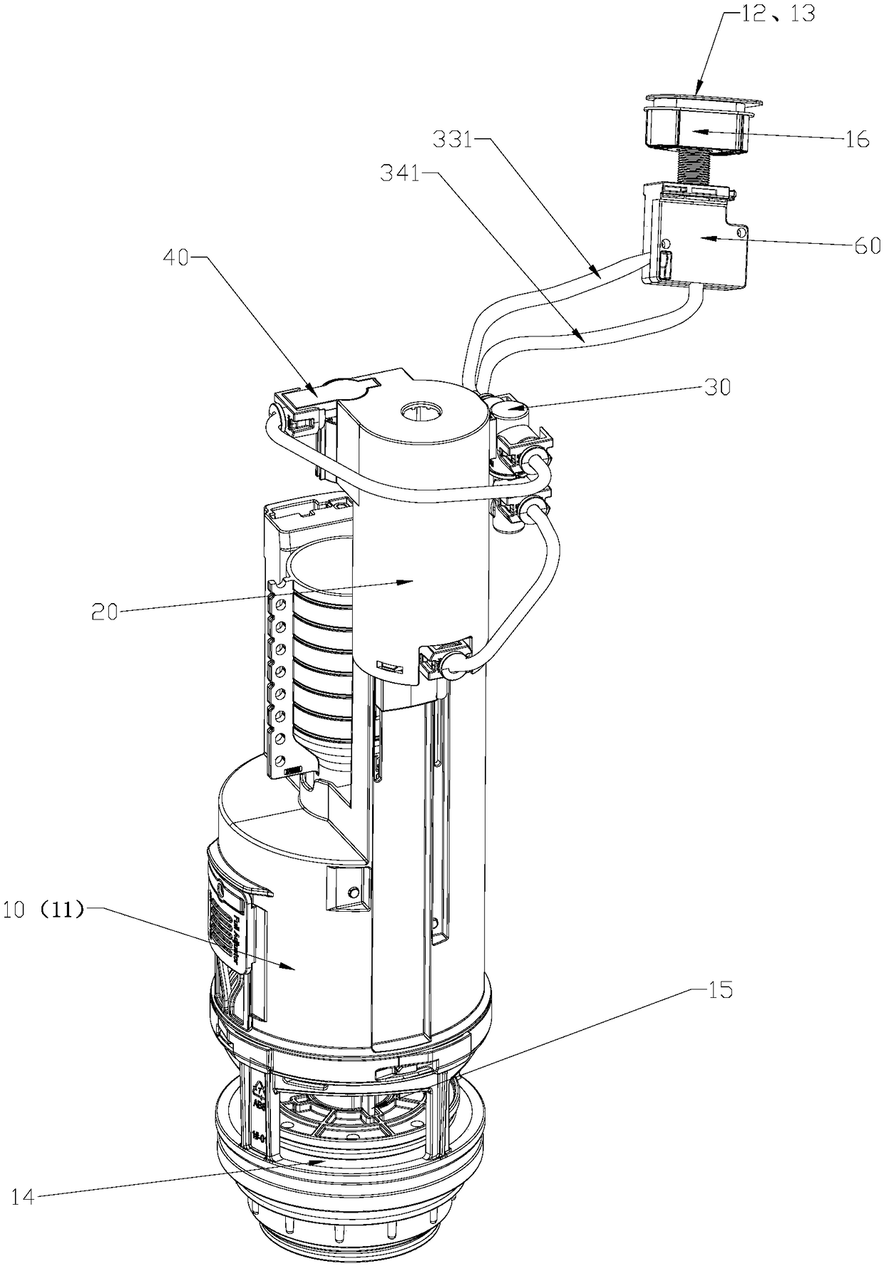
[0051] Such as Figure 1 to Figure 13 As shown, the air circuit control device of the pneumatic drain valve according to the first embodiment of the present invention includes a full drain switch 12 for controlling the drain valve 10 to start full drain, and a half drain switch 13 for controlling the drain valve 10 to start half drain , a switching valve 30 , an air supply source 60 , and a limiting member 50 .

[0052] Such as Figure 4 to Figure 6 As shown, the switching valve 30 includes a switching body 31 and a switching core 32, and the switching body 31 has a first air inlet 33, a second air inlet 34, a first air outlet 35, and a second air outlet 36; The switching core 32 is movably disposed in the switching body 31 ...

no. 2 example

[0066] The second embodiment (the stopper 50 is used to limit the full row of floating buckets of the drain valve, and the gas flowing out of the second air outlet 36 drives the stopper 50 to move from the limit position to the relief position)

[0067] The main difference between the air circuit control device of the pneumatic drain valve of the second embodiment of the present invention and the first embodiment is that the first embodiment controls the drainage by restricting or giving way to the movement of the valve core 15 by the limiting member 50 The valve performs half drainage or full drainage, but in this embodiment, the floating bucket of the full row of the drainage valve is restricted or given way by the limiter 50 to control the drainage valve to perform full drainage or half drainage, that is, this embodiment The principle of the drain valve realizing full drain and half drain is different from that of the first embodiment.

[0068] Specifically, in this embodim...

no. 3 example

[0070] The third embodiment (the stopper 50a is used to limit the movement stroke of the spool 15 of the drain valve, and the gas flowing out of the second air outlet 36 drives the stopper 50a to move from the abdication position to the limit position):

[0071] Such as Figure 14 and Figure 15 As shown, the air circuit control device of the pneumatic drain valve of the third embodiment of the present invention is mainly different from the first embodiment in that: in this embodiment, the limiting member 50a adopts a push rod that slides back and forth, and the first The gas flowing out from the second air outlet 36 is used to drive the limiting member 50a, so that the limiting member 50a moves from the evacuation position to the limiting position. Such as Figure 14 As shown, when the switching core 32 is in the first position, the limiting member 50a is located in the relief position, and the limiting member 50a makes way for the valve core 15 so that the drain valve 10 c...


PUM


Abstract

The invention discloses a pneumatic drain valve and an air channel control device thereof. A switching body of a switching valve of the pneumatic drain valve is provided with a first air inlet, a second air inlet, a first air outlet and a second air outlet; a switching core of the switching valve is movably arranged in the switching body; one of a half-drain switch and a full-drain switch controlsan air supply source to supply air to the first air inlet so that the switching core moves a first position, communicated with the first air outlet, of the first air inlet, the air flowing out from the first air outlet drives and controls the drain valve to correspondingly perform half drain or full drain; the other one of the half-drain switch and the full-drain switch controls the air supply source to supply air to the second air inlet so that the switching core moves a second position, communicated with the first air outlet and the second air outlet simultaneously, of the second air inlet,the air flowing out from the first air outlet and second air outlet jointly drives and controls the drain valve to correspondingly perform full drain or half drain; the structural layout is more flexible, and the operation is more convenient; the air channel switching can be achieved, and the function is more reliable.

Description

technical field [0001] The invention relates to a pneumatic drainage valve and an air circuit control device thereof. Background technique [0002] The drainage device of the common flushing water tank on the market usually adopts a mechanical opening structure, that is, a direct pressing drainage structure. This structure is generally composed of a pressing driving device (operating device) and a drainage device, and the pressing driving device is limited by the drainage device. As a result, the installation of the operating device is limited. In many applications, the user cannot perform the flushing action very conveniently, and needs to adjust the body position. What an inconvenience. [0003] In order to make full use of the living space, there are currently hidden water tanks hidden in the wall or in the bathroom cabinet. Therefore, the ordinary mechanical opening structure of the drain valve is no longer applicable. The connection between the drain valve and the oper...

Claims


Application Information

Patent Timeline
Patent Type & Authority Applications(China)
IPC IPC(8): E03D1/35
CPCE03D1/35
Inventor 陈起帆张荣誉王兴东
Owner XIAMEN R&T PLUMBING TECH
Why Eureka
Try Eureka