Antenna structure and communication device using the same

a technology of antenna structure and communication device, applied in the structure of radiating elements, elongated active elements, resonant antennas, etc., can solve the problems of unsuitable use of higher-order frequency bands in radio communication, inability to utilize higher-order frequency bands for radio communication,

Active Publication Date: 2006-11-14
MURATA MFG CO LTD
View PDF6 Cites 84 Cited by
  • Summary
  • Abstract
  • Description
  • Claims
  • Application Information

AI Technical Summary

Benefits of technology

[0013]To overcome the problems described above, preferred embodiments of the present invention provide an antenna structure suitable for multi-band radio communication of which the resonant frequency in the fundamental frequency band can be changed without hazardous effects on the resonant state of a higher-order frequency band, and a communication device provided with the antenna structure.
[0017]In particular, according to a preferred embodiment of the present invention, a capacitance is not rendered between the entire feed radiation electrode and the ground portion, but a capacitance may be locally rendered between the open end portion of the feed radiation electrode and the ground portion, and the capacitance between the open end portion of the feed radiation electrode and the ground portion may be changed. The capacitance between the open end portion of the feed radiation electrode and the ground portion significantly influences the resonant frequency in the fundamental frequency band. According to a preferred embodiment of the present invention, with the above-described configuration, the capacitance between the open end portion of the feed radiation electrode and the ground portion can be changed. Thereby; the resonant frequency in the fundamental frequency band can be changed. The capacitance between the open end portion of the feed radiation electrode and the ground portion also influences the resonant frequencies in a higher-order frequency band. However, it has been confirmed by experiments by the inventor of the present invention that the degree of influence is relatively small as compared to the influence on the fundamental frequency band. Since the degree with which the capacitance between the open end portion of the feed radiation electrode and the ground portion influences the resonant frequencies in the higher-order frequency band is small as described above, the resonant frequencies in the higher-order frequency band are not substantially changed when the capacitance between the open end portion of the feed radiation electrode and the ground portion is changed. Thus, the resonant state of the feed radiation electrode in the higher-order frequency band is not deteriorated.
[0020]Preferably, at least a portion of the feed radiation electrode is arranged on a dielectric substrate. Thus, the electrical length of the feed radiation electrode with respect to a signal for radio communication (high frequency signal) can be increased due to the wavelength shortening effect of the dielectric substrate. The feed radiation electrode having at least a portion arranged on the dielectric substrate can be reduced in effective length as compared to the feed radiation electrode not arranged on the dielectric substrate when the feed radiation electrodes have the same frequencies. Accordingly, the size of the antenna structure can be reduced by arranging at least a portion of the feed radiation electrode on the dielectric substrate.
[0022]Preferably, at least a portion of the feed radiation electrode is arranged on the dielectric substrate, and at least a portion of the non-feed radiation electrode is arranged on the same dielectric substrate. Thereby, the effective length of the feed radiation electrode and also the practical length of the non-feed radiation electrode can be reduced. Thus, the size of the antenna structure can be reduced.

Problems solved by technology

Thus, for example, in some cases, the higher-order frequency band is unsuitable for use in radio communication because of the insufficient bandwidth.
Thus, the higher-order frequency band cannot be utilized for radio communication.
That is, problems occur since the antenna structure 1 cannot function as an antenna suitable for multi-band communication.

Method used


Image

  • Antenna structure and communication device using the same
  • Antenna structure and communication device using the same
  • Antenna structure and communication device using the same

Examples


Embodiment Construction

[0038]Hereinafter, an antenna structure according to preferred embodiments of the present invention will be described with reference to drawings. The same components or elements as those of an antenna structure shown in FIGS. 6A and 6B are designated by the same reference numerals, and the description thereof is omitted.

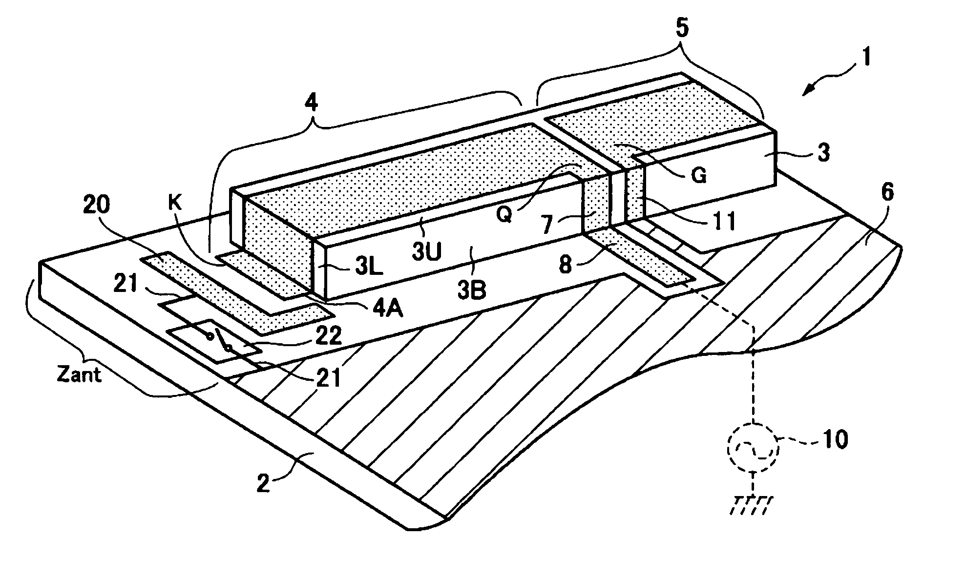
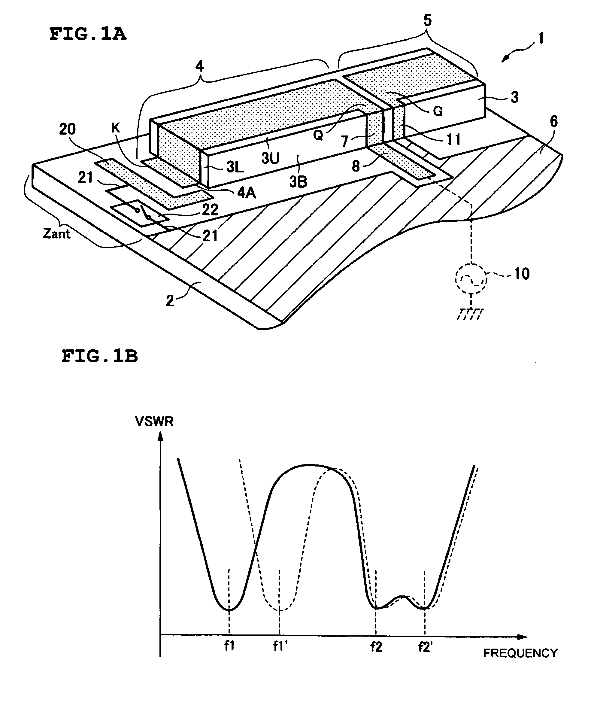
[0039]FIG. 1A is a schematic perspective view of an antenna structure according to a first preferred embodiment of the present invention. The antenna structure 1 of the first preferred embodiment includes a dielectric substrate 3 disposed on a base plate 2, a feed radiation electrode 4, a non-feed radiation electrode 5, and a ground portion 6, similarly to the antenna structures shown in FIGS. 6A and 6B.

[0040]According to the first preferred embodiment, a ground-side electrode 20 is arranged so as to be opposed, at an interval, to an open end portion K of the feed radiation electrode 4 on the surface of the base plate 2. The ground-side electrode 20 and the open end ...


PUM


Abstract

An antenna structure includes a capacitance-rendering portion located between an open end portion of a feed radiation electrode and a ground portion. A switch for changing the capacitance between the open end portion of the feed radiation electrode and the ground portion rendered by the capacitance-rendering portion is provided. When the capacitance between the open end portion of the feed radiation electrode and the ground portion is increased by the capacitance-rendering portion, a resonant frequency in the fundamental frequency band, caused by the antenna operation of the feed radiation electrode, is reduced corresponding to the increased amount of the capacitance. When the capacitance between the open end portion of the feed radiation electrode and the ground portion is decreased by the changing operation of the capacitance-rendering portion, the resonant frequency in the fundamental frequency band is increased corresponding to the decreased amount of the capacitance.

Description

BACKGROUND OF THE INVENTION[0001]1. Field of the Invention[0002]The present invention relates to an antenna structure suitable for multi-band radio communication which is performed in a plurality of different frequency bands, and to a communication device including the same.[0003]2. Description of the Related Art[0004]FIG. 6A is a schematic perspective view showing an example of an antenna structure suitable for multi-band radio communication which is performed in a plurality of different frequency bands. The antenna structure 1 includes a base plate 2 (e.g., a circuit board of a communication device), a dielectric substrate 3 mounted on one side end portion of the base plate 2, a feed radiation electrode 4, a non-feed radiation electrode 5, and a ground portion 6 provided on the base plate 2.[0005]The feed radiation electrode 4 and the non-feed radiation electrode 5 are λ / 4 type electrodes. An area Zant on the base plate 2 where the feed radiation electrode 4 and the non-feed radia...

Claims


Application Information

Patent Timeline
Patent Type & Authority Patents(United States)
IPC IPC(8): H01Q1/24H01Q1/38H01Q5/10H01Q9/14H01Q9/28H01Q9/36H01Q9/40
CPCH01Q9/285
Inventor YAMAKI, KAZUHISA
Owner MURATA MFG CO LTD
Why Eureka
Try Eureka