
Driving assist system for vehicle

Inactive Publication Date: 2006-11-14
NISSAN MOTOR CO LTD
View PDF31 Cites 27 Cited by
  • Summary
  • Abstract
  • Description
  • Claims
  • Application Information

AI Technical Summary

Benefits of technology

[0005]With such a vehicle driving assist system, it is wished to reliably convey the risk potential in the vehicle surroundings to the driver as a reaction force generated when a vehicle operation equipment is operated while making it possible for the driver to easily understand which obstacle is taken as a target obstacle in the reaction force control.

Problems solved by technology

Then, the system inhibits a steering operation that would lead to an undesirable situation by controlling the steering assist torque based upon the calculated risk potential.

Method used


Image

  • Driving assist system for vehicle
  • Driving assist system for vehicle
  • Driving assist system for vehicle

Examples


first embodiment

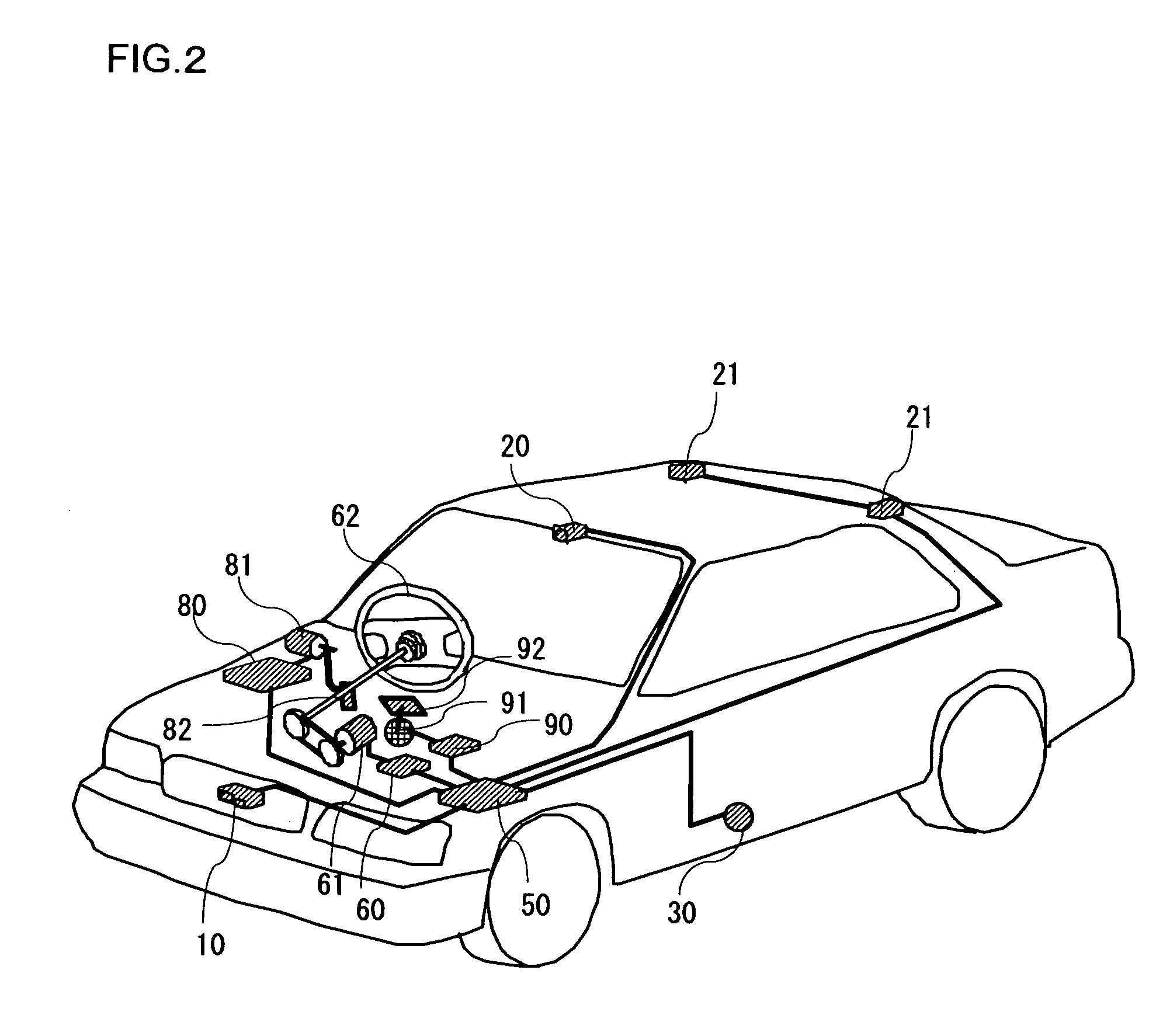
[0023]A vehicle driving assist system according to the first embodiment of the present invention will be described referring to the drawings. FIG. 1 shows the structure of a vehicle driving assist system 1 of the first embodiment of the present invention, and FIG. 2 is a structural diagram of a vehicle fitted with the vehicle driving assist system 1.

[0024]First of all, the structure of the vehicle driving assist system will be described.

[0025]A laser radar 10 is attached to a front grill of the vehicle or to a bumper etc., and propagates infrared pulses in a forward horizontal direction for scanning. The laser radar 10 measures reflected radiation of infrared pulses reflected by a plurality of reflecting objects ahead, such as the rear of a vehicle in front, and detects a distance (inter-vehicle distance) from the subject vehicle to a preceding vehicle, a relative velocity (relative speed) of vehicles and a direction along which the preceding vehicle is present based on the elapsed ...

second embodiment

[0082]Next, a vehicle driving assist system according a second embodiment of the present invention will be described. The structure of the vehicle driving assist system of the second embodiment is identical to that of the first embodiment. Here, explanation will focus on points that differentiate the second embodiment from the first embodiment.

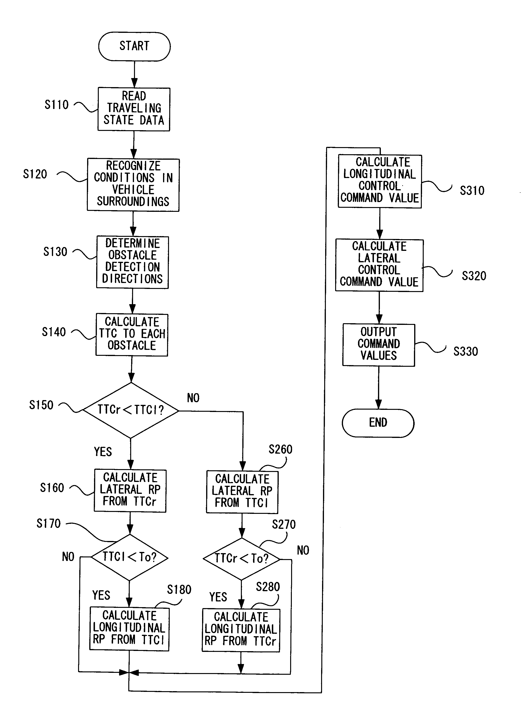
[0083]In the second embodiment, obstacles that exist on the two obstacle detection directions forward of the subject vehicle are detected as described in the first embodiment. The reaction force controls in the lateral and longitudinal direction of the subject vehicle are then performed in accordance with the time to contact TTCr and TTCl to each obstacle. In the second embodiment, the reaction force control in the longitudinal direction of the subject vehicle is performed only when the same obstacle is detected in both the right obstacle detection direction and the left obstacle detection direction.

[0084]Explanations will be given as to how r...


PUM


Abstract

In a vehicle driving assist system, an obstacle detection device detects an obstacle present in each of two obstacle detection directions with respect to a subject vehicle; and a TTC calculation device calculates a TTC between the subject vehicle and each of obstacles based on detection results of the obstacle detection device. A lateral reaction force control device controls a reaction force generated at a vehicle operation equipment for drive operation in a lateral direction of the subject vehicle based on a first TTC which is smaller in the TTCs calculated in the TTC calculation device; and a longitudinal reaction force control device controls a reaction force generated at a vehicle operation equipment for drive operation in a longitudinal direction based on a second TTC which is larger in the TTCs.

Description

BACKGROUND OF THE INVENTION[0001]1. Field of the Invention[0002]The present invention relates to a technology for assisting driver operations, and more specifically, it relates to a driving assist system for a vehicle that assists operations performed by the driver.[0003]2. Description of Related Art[0004]Systems employed to assist driver operations in the related art include the system disclosed in Japanese Laid Open Patent Publication No. H10-211886. This system detects obstacles present around the vehicle and determines any latent risk potential that may exist. Then, the system inhibits a steering operation that would lead to an undesirable situation by controlling the steering assist torque based upon the calculated risk potential.SUMMARY OF THE INVENTION[0005]With such a vehicle driving assist system, it is wished to reliably convey the risk potential in the vehicle surroundings to the driver as a reaction force generated when a vehicle operation equipment is operated while mak...

Claims


Application Information

Patent Timeline
IPC IPC(8): G06F19/00B60R21/00B60K26/02B60K28/14B60T8/00B60W10/04B60W10/06B60W10/18B60W10/188B60W10/20B60W30/00B60W30/09B60W40/105B60W40/114B60W50/14B60W50/16B62D6/00B62D101/00B62D113/00G08G1/16
CPCG08G1/16B60K26/021B60K31/0008G08G1/166G08G1/167
Inventor YAMAMURA, TOMOHIRO
Owner NISSAN MOTOR CO LTD
Learn More