Parallel configuration composite material fabricator

a fabricator and parallel configuration technology, applied in the direction of mechanical control devices, controlling lamination, process and machine control, etc., can solve the problems of time-consuming and cost-intensive fabrication, non-uniform lay-up, and slow batch processing of known automated tape laminating devices

Inactive Publication Date: 2006-11-21
THE BOEING CO
View PDF62 Cites 149 Cited by
  • Summary
  • Abstract
  • Description
  • Claims
  • Application Information

AI Technical Summary

Problems solved by technology

This method of fabrication is time consuming and cost intensive, and could possibly result in non-uniformity in the lay-up.
The batch processing employed in known automated tape laminating devices can be slow, tedious, and cumbersome.

Method used


Image

  • Parallel configuration composite material fabricator
  • Parallel configuration composite material fabricator
  • Parallel configuration composite material fabricator

Examples


Embodiment Construction

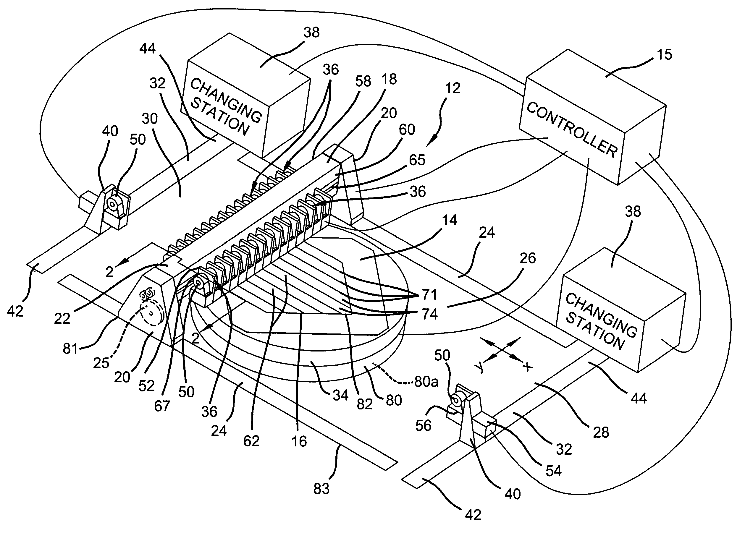
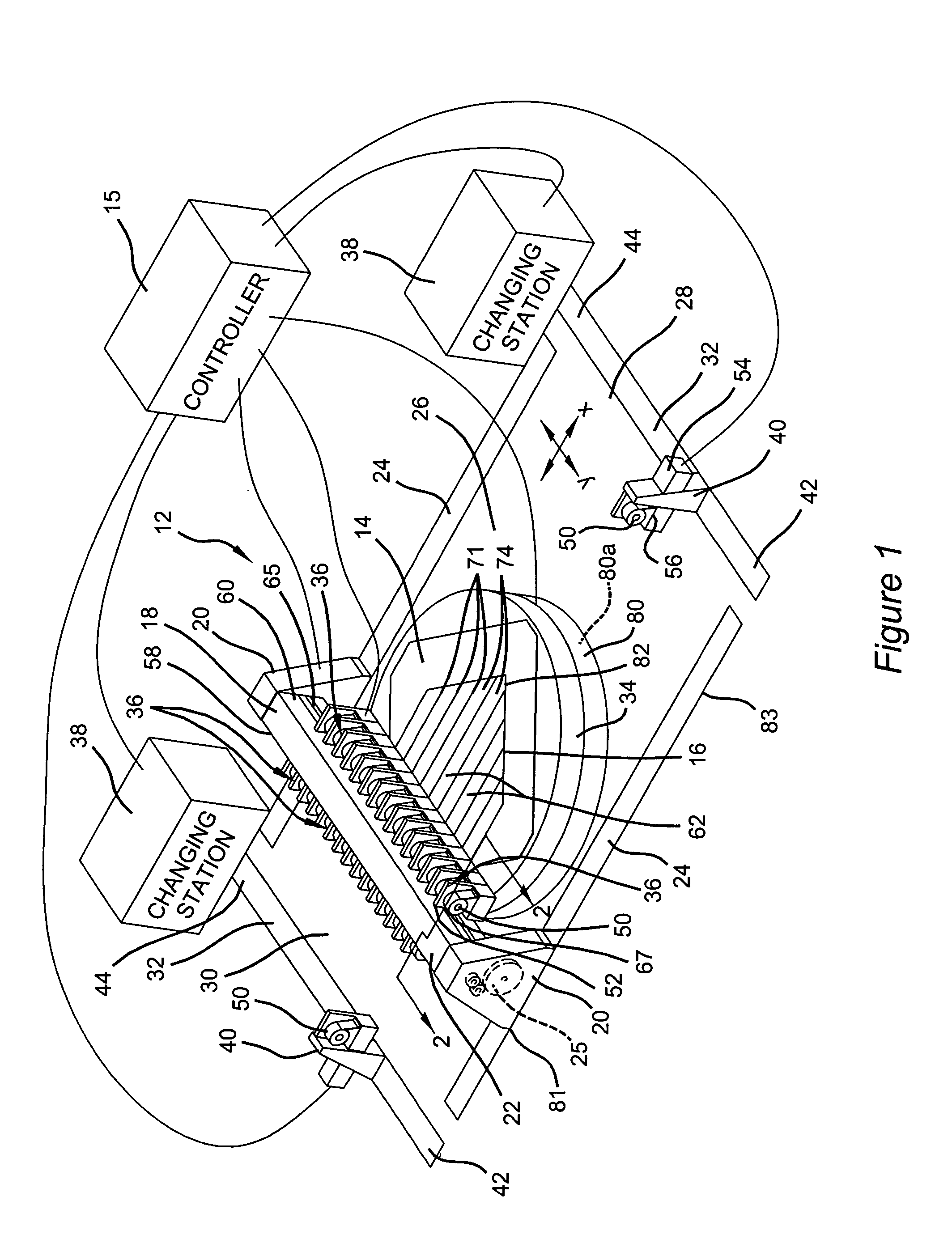
[0018]With reference to FIG. 1, a composite fabrication device constructed in accordance with the teachings of the present invention is generally indicated by the reference numeral 12. In the particular embodiment illustrated, the composite fabrication device 12 includes a structure 14 having a work surface datum (i.e., a work surface) 16. The composite fabrication device 12 has a gantry 18 elevated over the work surface datum 16. In the example provided, the gantry 18 includes two vertical beams 20 and a bridge rail 22. Those skilled in the art will appreciate, however, that the gantry 18 may be constructed in numerous other ways including a pair of overhead runways or beams (not shown) that support the opposite ends of the bridge rail 22.

[0019]The vertical beams 20 are associated with a pair of tracks 24 that bound the opposite sides of a working area 26. For purposes of discussion, the tracks 24 define a X-axis that is generally perpendicular to a Y-axis defined by the bridge rai...


PUM

PropertyMeasurementUnit
widthaaaaaaaaaa
widthaaaaaaaaaa
widthaaaaaaaaaa

Abstract

A device for fabricating a composite article having a plurality of material dispensers to increase productivity. The device includes a structure defining a work surface datum, the plurality of material dispensers which are movable relative to the structure, where each of the material dispensers applies a strip material to the work surface datum along a predetermined axis, and wherein each of said predetermined axes are parallel to one another and where the strip material as applied to the work surface datum forms a layer. A method for fabricating a composite in accordance with the present invention is also provided.

Description

FIELD OF THE INVENTION[0001]The present invention generally relates to devices and methods for the fabrication of articles from composite materials.BACKGROUND OF THE INVENTION[0002]Articles that are formed partially or wholly from composite materials (herein after referred to as “composite articles”) are employed in a vast number of fields, usually to provide the finished article with desired characteristics, such as a relatively low weight and a relatively high strength. One method of fabricating composite articles includes the use of strips of a composite material, such as a graphite tape or cloth, to form what is known in the art as a composite “lay-up”. The lay-up includes one or more layers, with each layer being formed from touching and / or overlapping strips of the material. A resin, which may be pre-impregnated in the material or later injected into one or more of the layers of material, is later processed to cure the lay-up such that the material strips are bonded together. ...

Claims


Application Information

Patent Timeline
Patent Type & Authority Patents(United States)
IPC IPC(8): B21D39/03B29C70/08B32B37/00B29C70/20B29C70/22B29C70/32B29C70/34B29C70/38
CPCB29C70/207B29C70/386B29C70/545B29C70/202B29C70/088Y10T156/1348B29C70/222B29C70/32B29C70/34B29C2793/0081B29K2105/08B29K2105/0809B29K2105/108B29K2705/00B29K2707/04B29K2709/08B29K2711/12Y10T156/1084Y10T156/1788Y10T29/49826Y10T156/1057Y10T29/53526Y10T156/1097Y10T156/1077Y10T29/49885
Inventor NELSON, PAUL E.
Owner THE BOEING CO
Why Eureka
Try Eureka