
Electric-hydraulic power unit

a technology of electric-hydraulic power units and power units, which is applied in the direction of positive-displacement liquid engines, piston pumps, borehole/well accessories, etc., can solve the problems of small-bore check valves, easy damage or debris, and is not practical to replace hydraulic scssv actuators with less robust electric actuators

Active Publication Date: 2006-11-21
FMC TECH INC
View PDF24 Cites 47 Cited by
  • Summary
  • Abstract
  • Description
  • Claims
  • Application Information

AI Technical Summary

Benefits of technology

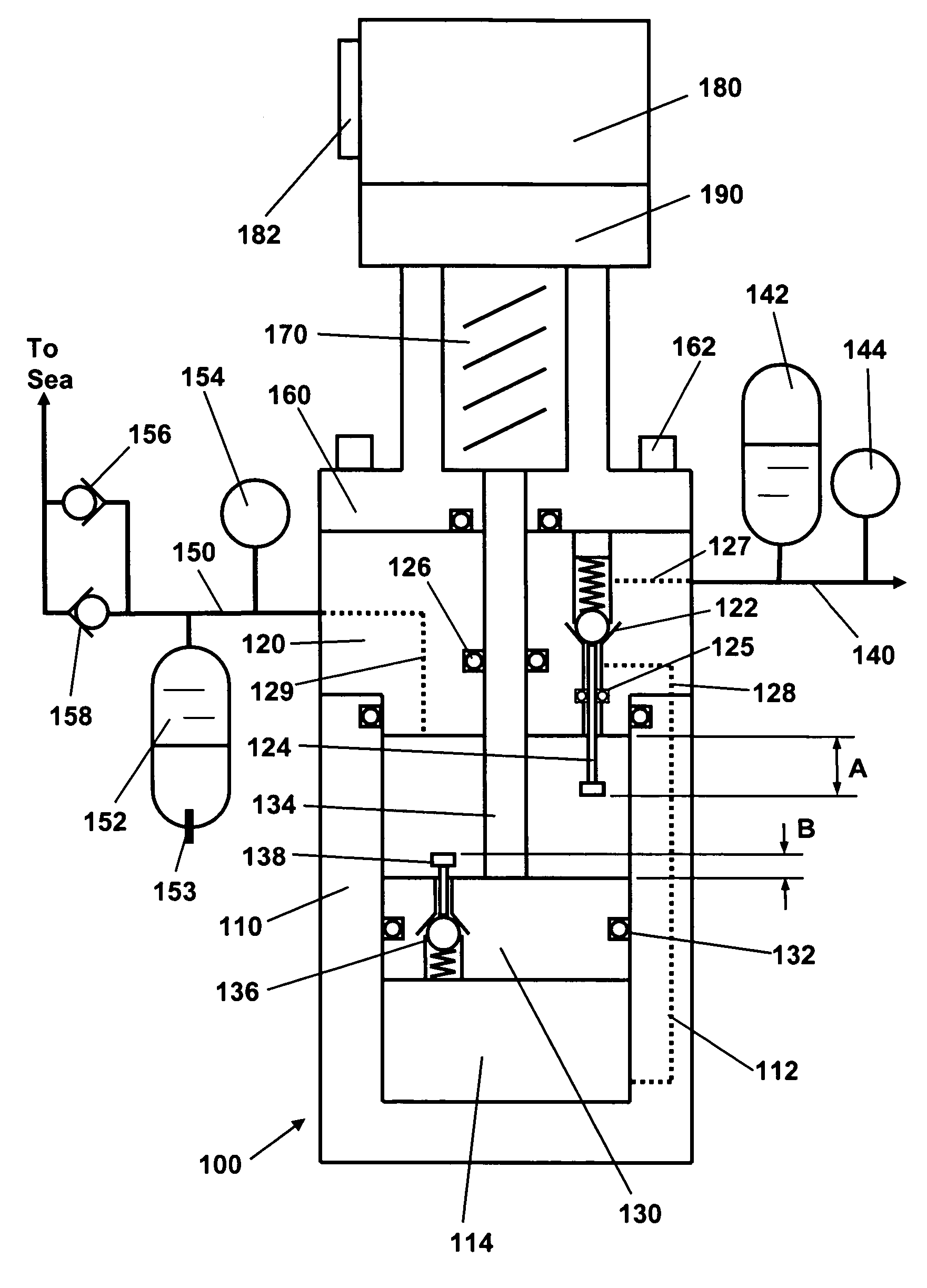
The present invention is an electric-hydraulic power unit that includes a body with a movable pressure barrier positioned therein. The movable pressure barrier defines chambers within the body and a configurable flow path in fluid communication with the chambers. The device also includes a valve that can be configured in different states to allow fluid to flow in either direction between the chambers. The device can also be powered by an electric motor and can create a resistance force to a pressure force created by a pressure existing in the chamber. The device can be used in various applications such as in hydraulic power systems.

Problems solved by technology

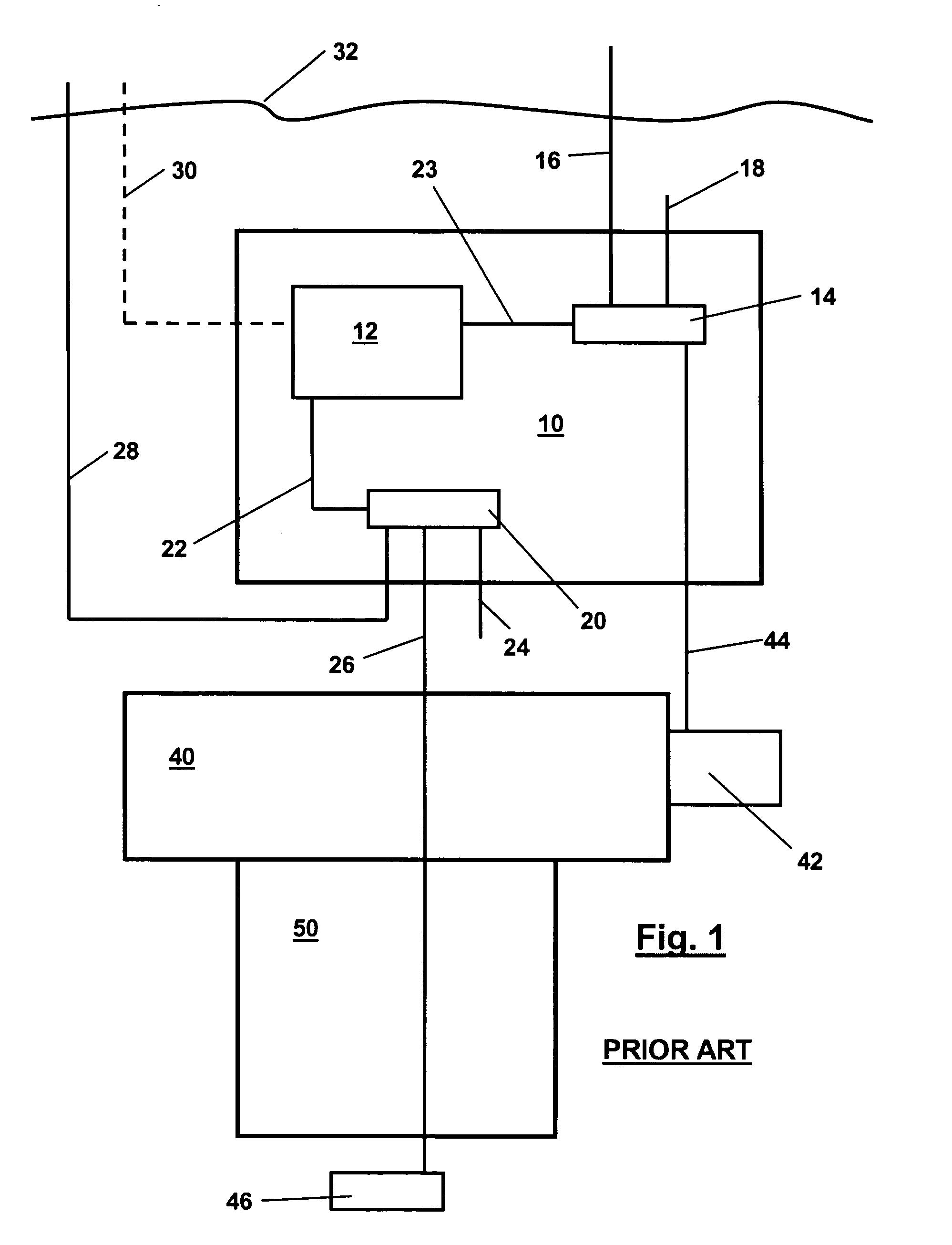
Typically, solenoid valves such as 20 are relatively large, complex, and expensive devices.
Each such valve may include ten or more extremely small-bore check valves, which are easily damaged or clogged with debris.
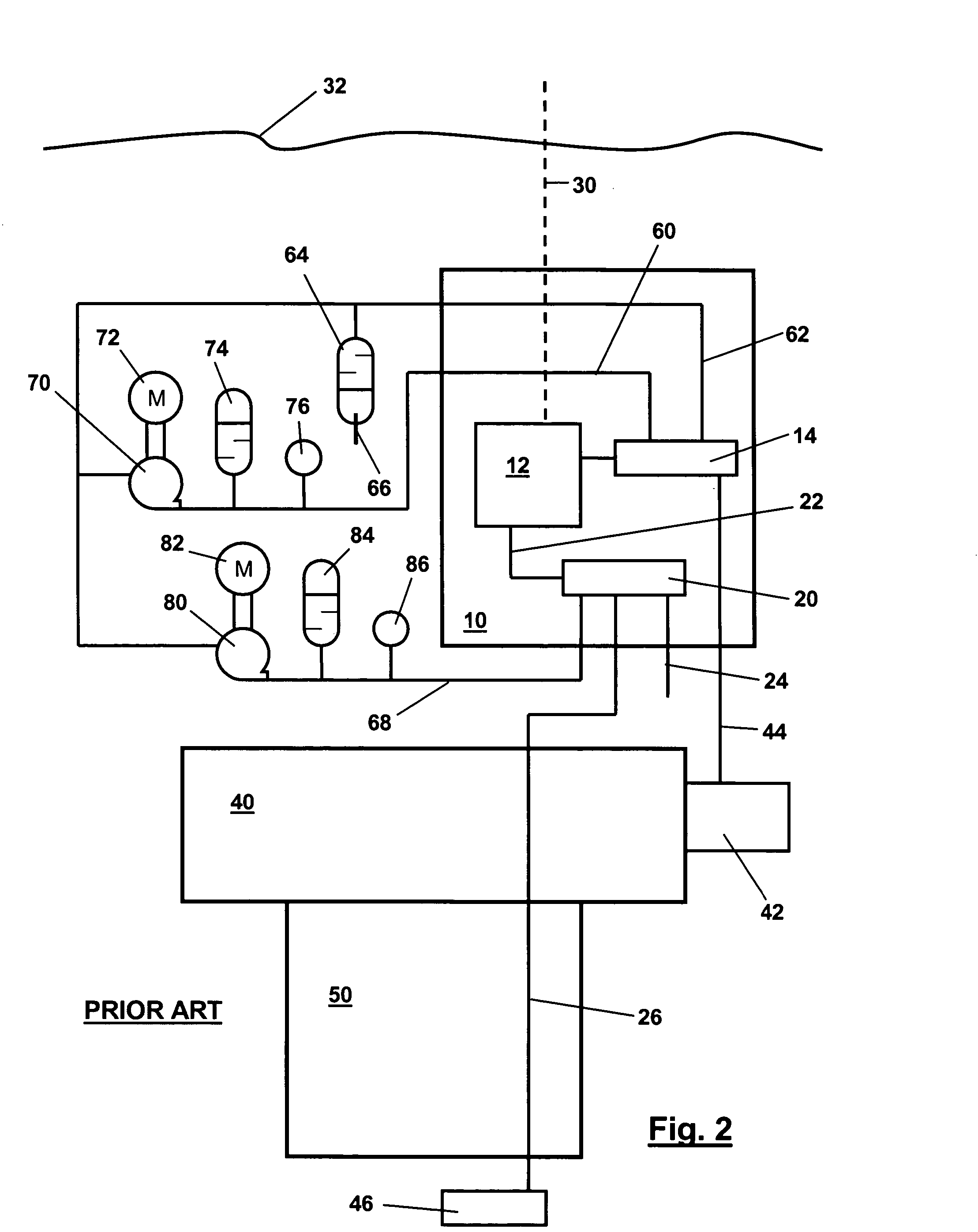
However, in the system of FIG. 2, high and low-pressure hydraulic fluid is provided by independent subsea-deployed pumping systems.
However, SCSSV's are required equipment in many locations, and thus cannot be omitted from all systems.
Also, because of the harsh downhole environment, it is not practical to replace the hydraulic SCSSV actuators with less robust electric actuators.

Method used


Image

  • Electric-hydraulic power unit
  • Electric-hydraulic power unit
  • Electric-hydraulic power unit

Examples


Embodiment Construction

[0031]Illustrative embodiments of the invention are described below. In the interest of clarity, not all features of an actual implementation are described in this specification. It will of course be appreciated that in the development of any such actual embodiment, numerous implementation-specific decisions must be made to achieve the developers' specific goals, such as compliance with system-related and business-related constraints, which will vary from one implementation to another. Moreover, it will be appreciated that such a development effort might be complex and time-consuming, but would nevertheless be a routine undertaking for those of ordinary skill in the art having the benefit of this disclosure.

[0032]The present invention will now be described with reference to the attached figures. The words and phrases used herein should be understood and interpreted to have a meaning consistent with the understanding of those words and phrases by those skilled in the relevant art. No...


PUM


Abstract

The present invention is directed to an electric-hydraulic power unit. In one illustrative embodiment, the power unit comprises a body having a movable pressure barrier positioned therein, the movable pressure barrier defining first and second chambers therein, a configurable flow path in fluid communication with the first and second chambers, and at least one valve for configuring the flow path in a first state wherein fluid may flow within the flow path only in a direction from the first chamber toward the second chamber, and a second state wherein fluid within the flow path may flow in both directions between the first and second chambers.

Description

BACKGROUND OF THE INVENTION[0001]1. Field of the Invention[0002]The present invention relates to a hydraulic power unit (HPU). More specifically, the present invention relates to an electrically powered HPU having a hydraulically operated failsafe mechanism. In one illustrative embodiment, the present invention is directed to a subsea HPU.[0003]2. Description of the Related Art[0004]A typical subsea wellhead control system, shown schematically in FIG. 1, includes a subsea tree 40 and tubing hanger 50. A high-pressure hydraulic line 26 runs downhole to a surface-controlled subsea safety valve (SCSSV) actuator 46, which actuates an SCSSV. A subsea control module (SCM) 10 is disposed on or near the tree 40. The SCM includes an electrical controller 12, which communicates with a rig or vessel at the surface 32 via electrical umbilical 30.[0005]Through control line 22, the controller 12 controls a solenoid valve 20, which in turn controls the flow of high-pressure hydraulic fluid from hy...

Claims


Application Information

Patent Timeline
Patent Type & Authority Patents(United States)
IPC IPC(8): E21B34/04E21B33/00E21B33/035F15B1/26F15B21/04
CPCE21B33/0355F15B1/265F15B21/006F04B7/0053F04B7/0057F04B17/03F15B1/024F15B1/033F15B1/04
Inventor JOHANSEN, JOHN A.HALVORSEN, VIDAR STENWILLIAMS, MICHAEL R.
Owner FMC TECH INC
Learn More