
In-flight refueling system, sensor system and method for damping oscillations in in-flight refueling system components

a technology of in-flight refueling and sensor system, which is applied in the direction of instruments, distance measurement, aircraft power plants, etc., can solve the problems of increased danger, potential danger, and mid-air collision between aircra

Inactive Publication Date: 2006-11-21
THE BOEING CO
View PDF5 Cites 33 Cited by
  • Summary
  • Abstract
  • Description
  • Claims
  • Application Information

AI Technical Summary

Benefits of technology

The present invention provides an in-flight refueling system, sensor system, and method that can resist changes in the position of the elongate hose during refueling operations. The sensor system is operably engaged with the hose and can detect and transmit signals indicating changes in its position, which are then received and converted into a control input for the retracting device. This allows for quick retraction of the hose to prevent the changes in its position. The sensor system may include an accelerometer or other motion detecting device to detect changes in the hose's position and an optical source and receiver for transmitting and receiving the optical signals. The invention provides many advantages, including but not limited to providing a system that can resist changes in the hose's position, providing a sensor device that can detect and transmit signals remotely to the retracting device, and providing a sensor device that can be easily integrated with the hose or drogue.

Problems solved by technology

Although in-flight refueling is a relatively common operation, especially for military aircraft, the passage of large amounts of fuel between a first aircraft (the tanker aircraft, for instance) and a second aircraft (the receiver aircraft, for instance) during an in-flight refueling operation may create a potentially dangerous situation, especially if components of the in-flight refueling system are allowed to move or oscillate in an uncontrolled manner.
In addition, the close proximity of the first aircraft and the second aircraft during an in-flight refueling operation may create the danger of a mid-air collision between the aircraft.
Such a danger may be increased if a component of an in-flight refueling system extending from the first aircraft is allowed to oscillate or move in an erratic manner relative to the first aircraft.
In both of these cases, the elongate hose may be exposed to high wind speeds as it is trailed behind the first aircraft.
As in all mechanical systems, however, the elongate hose and attached drogue may experience oscillatory vibrations in response to applied forces (such as for instance, wind forces, or the impact force encountered as the second aircraft engages the drogue).
In some cases, the elongate hose (and attached drogue) may begin to oscillate uncontrollably (at for instance, a resonance frequency) with respect to the first aircraft such that the drogue may move in an erratic pattern with respect to the first aircraft such that it may become difficult for an operator of the second aircraft to maneuver the second aircraft such that the refueling probe extending therefrom may be engaged with the drogue.
Such motion may not only make the in-flight refueling operation difficult but also endanger both the first and second aircraft if the motion becomes extreme.
The safety of the crews that may operate the first and second aircraft may be in danger if the elongate hose and attached drogue begin to impact the control surfaces, in-flight refueling system pod, or other structural components of the first or second aircraft.
However, it is undesirable to jettison the elongate hose and attached drogue as the first aircraft must cease in-flight refueling operations and return to an airfield for costly and complex repairs to the in-flight refueling system.
Also, it is especially undesirable to jettison the elongate hose while the second aircraft is engaged with the attached drogue, as a length of elongate hose may be left hanging from the refueling receptacle carried by the second aircraft and may damage the second aircraft by striking a control surface or by being taken into a jet intake of the second aircraft.
Such sensors have limited capacity to limit the damage that may be caused by traveling waves, however, as slack in the elongate hose may not be detected until the traveling wave has already reached the sensor, by which time, the elongate hose may have already struck and damaged the tanker aircraft or the in-flight refueling system pod carrying the sensor and take-up device.

Method used


Image

  • In-flight refueling system, sensor system and method for damping oscillations in in-flight refueling system components
  • In-flight refueling system, sensor system and method for damping oscillations in in-flight refueling system components
  • In-flight refueling system, sensor system and method for damping oscillations in in-flight refueling system components

Examples


Embodiment Construction

[0021]The present inventions now will be described more fully hereinafter with reference to the accompanying drawings, in which some, but not all embodiments of the invention are shown. Indeed, these inventions may be embodied in many different forms and should not be construed as limited to the embodiments set forth herein; rather, these embodiments are provided so that this disclosure will satisfy applicable legal requirements. Like numbers refer to like elements throughout.

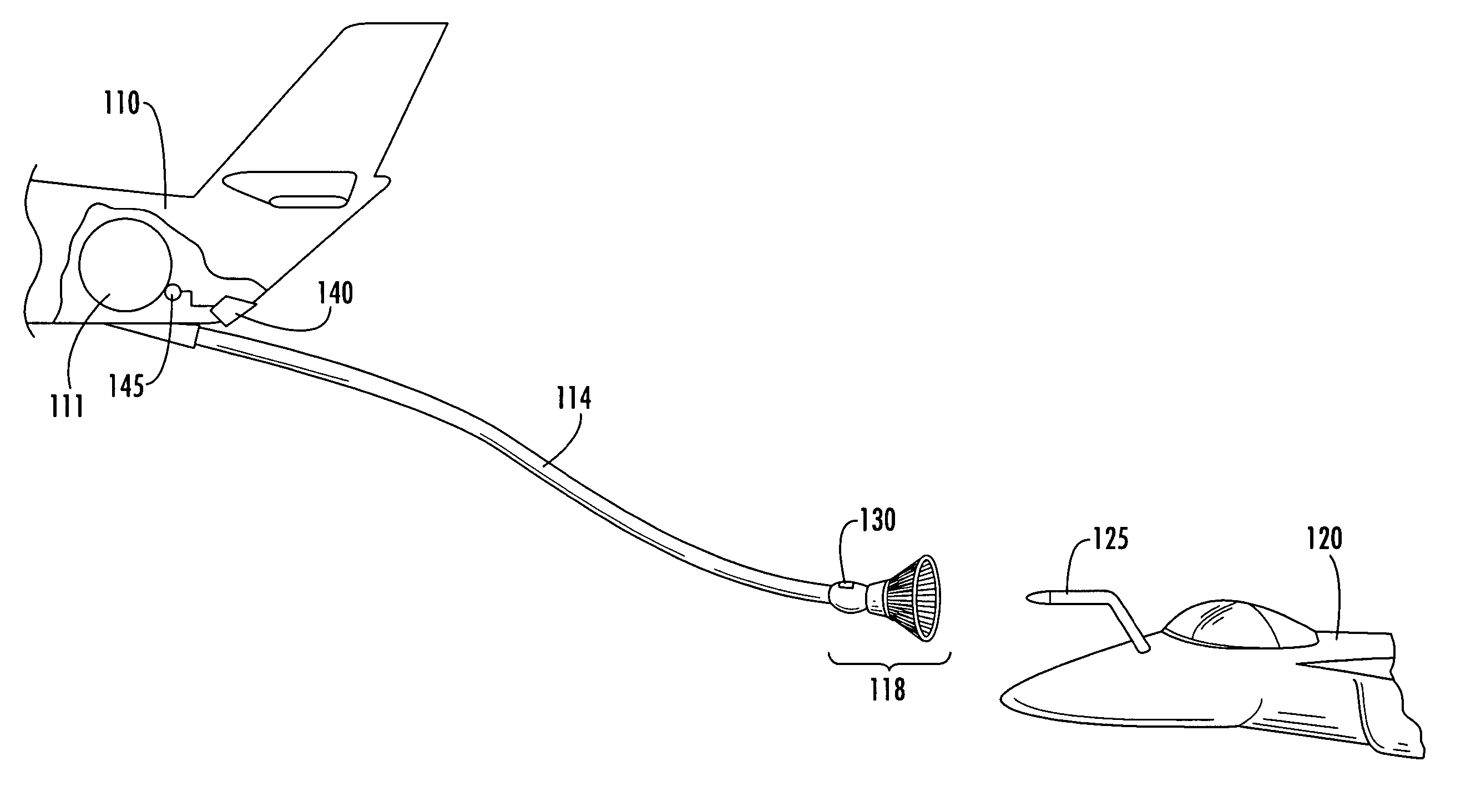
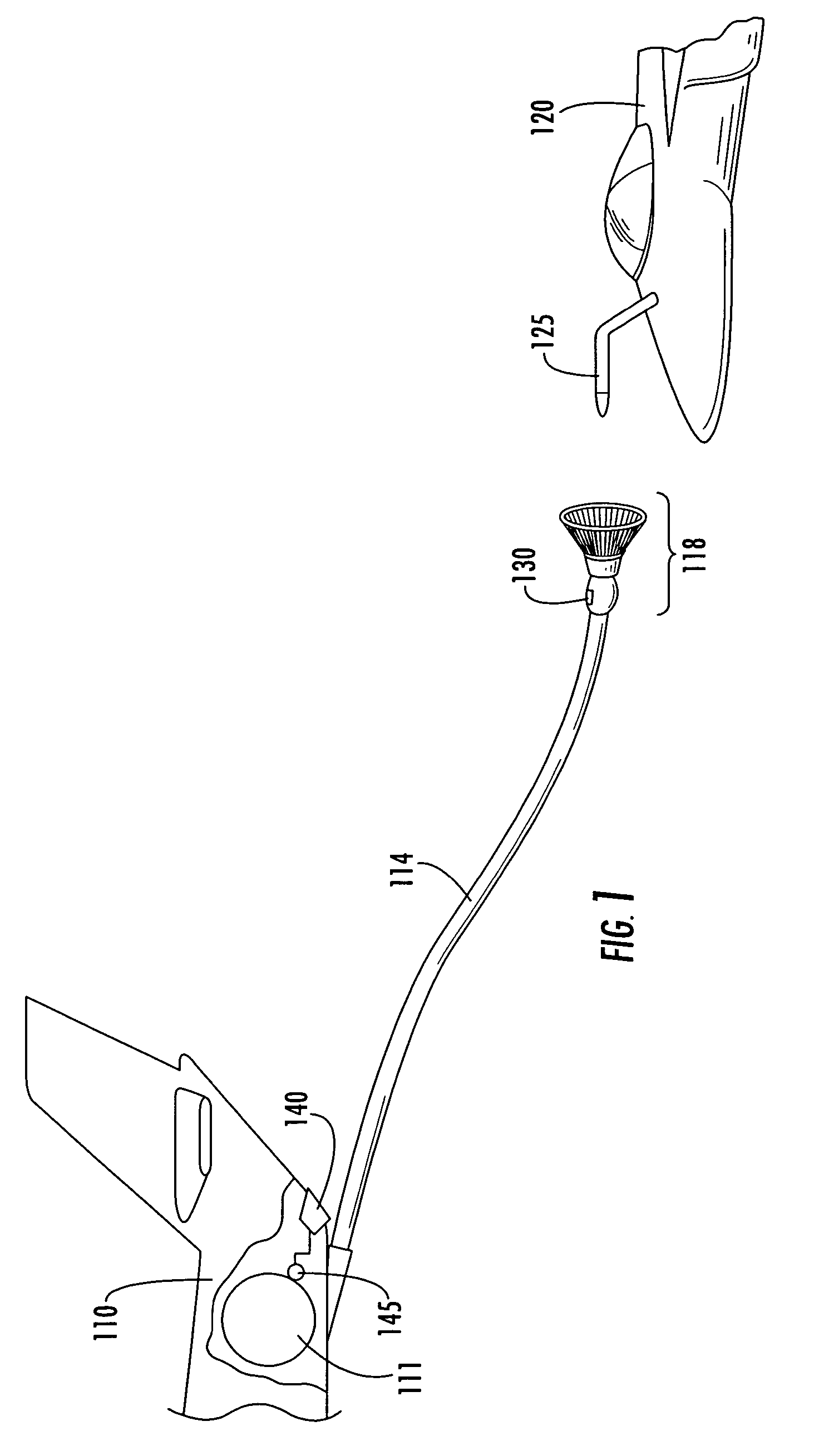
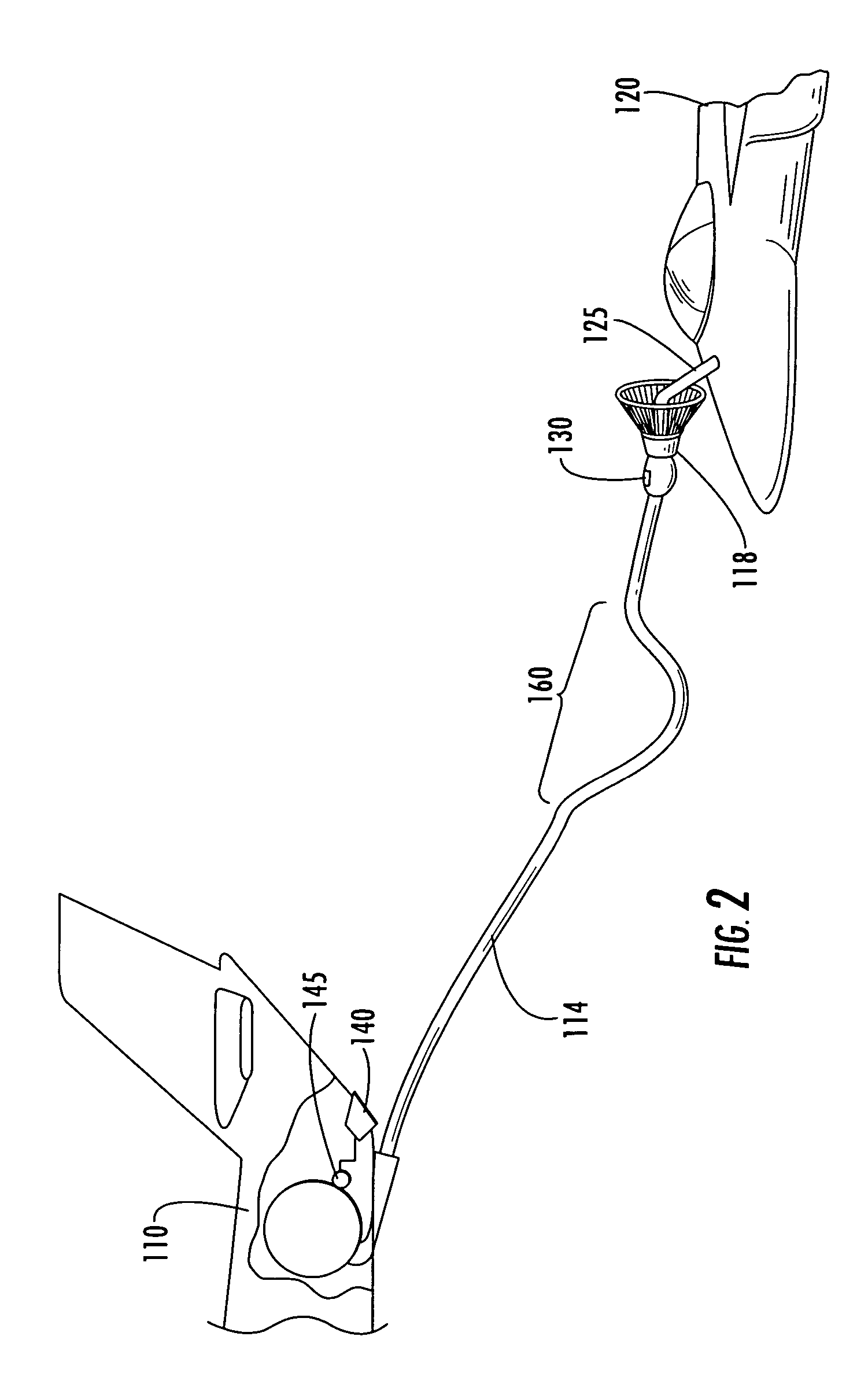
[0022]FIG. 1 shows an in-flight refueling system according to one embodiment of the present invention including a tanker aircraft 110 and an elongate hose 114 extending therefrom. The elongate hose 114 comprises a first end (not shown) that is carried by the tanker aircraft 110 and may be operably engaged with a fuel reservoir located within a fuselage, wing structure, or other internal compartment within the tanker aircraft 110. In some embodiments, the first end of the elongate hose 114 may further be operabl...


PUM


Abstract

An in-flight refueling system, sensor system and method are provided for detecting and damping changes in the disposition of an elongate hose extending from a tanker aircraft during an in-flight refueling operation. The various embodiments provide a compact, lightweight, and low-profile sensor device that may be fitted to the elongate hose so as to detect oscillations in the elongate hose and transmit a signal to a hose retracting device carried by the tanker aircraft such that the hose retracting device retracts the elongate hose in response to the signal so as to counteract the occurrence of oscillations within the elongate hose. Thus, these embodiments may minimize the effect of oscillations in the elongate hose by selectively retracting the elongate hose in response to oscillations detected therein as it extends from the tanker aircraft during an in-flight refueling operation.

Description

FIELD OF THE INVENTION[0001]The present invention relates generally to in-flight refueling of a manned or unmanned aircraft using a probe and drogue in-flight refueling system, and specifically, providing a sensor system having the capability of communicating with a hose take-up device carried by a tanker aircraft. The hose take-up device may further be configured to extend and retract an elongate hose and attached drogue that may be trailed behind the tanker aircraft as part of an in-flight refueling operation. More particularly the present invention relates to the provision and placement of a sensor device near the drogue end of the elongate hose, wherein the sensor device is capable of sending data related to changes in disposition of the drogue end of the elongate hose in real time to the hose take-up device such that the elongate hose may be more rapidly retracted relative to the tanker aircraft so as to resist changes in the disposition of the elongate hose that may occur duri...

Claims


Application Information

Patent Timeline
Patent Type & Authority Patents(United States)
IPC IPC(8): G01C3/00B64D37/00
CPCB64D39/02B64D39/00
Inventor VON THAL, GERMAN
Owner THE BOEING CO
Learn More