Sterile connector

a connector and connector technology, applied in the field of sterile connectors, can solve the problems of increasing the risk of contamination of the entire system, not always possible, and using steam,

Active Publication Date: 2006-11-21
MILLIPORE CORP
View PDF15 Cites 62 Cited by
  • Summary
  • Abstract
  • Description
  • Claims
  • Application Information

AI Technical Summary

Problems solved by technology

It would be desirable to have a completely sealed system but this is not always possible with the processes that take place in production.
Several disadvantages exist with the use of steam.
This increases the risk of contamination of the entire system.
Also the high temperatures and pressure differentials of the steam make the selection of materials and components very difficult and limited and even then an accidental pressure differential at high temperatures can cause a non-steel component to fail.
Additionally, such systems that are reused need to undergo rigorous testing and validation to prove to the necessary authorities that the system is sterile before each use.
The expense of validation as well as the cleaning regiment required is very high and very time consuming (typically taking 1 to 2 years for approval).
In addition, some components are very difficult to adequately clean after use.
While this may significantly reduce the presence of organisms, it does not eliminate them and at best this provides an aseptic connection.
This approach is cumbersome and there is still some risk of contamination in the removal of the outer membranes.
Also the use of piercing device creates the generation of particles that are unacceptable as well as the potential for tearing the seals between the two components that might add more contaminants to the system or clog the openings.
Lastly, the device is limited in size making its use at large volumes or flows impracticable.

Method used


Image

  • Sterile connector
  • Sterile connector
  • Sterile connector

Examples


Embodiment Construction

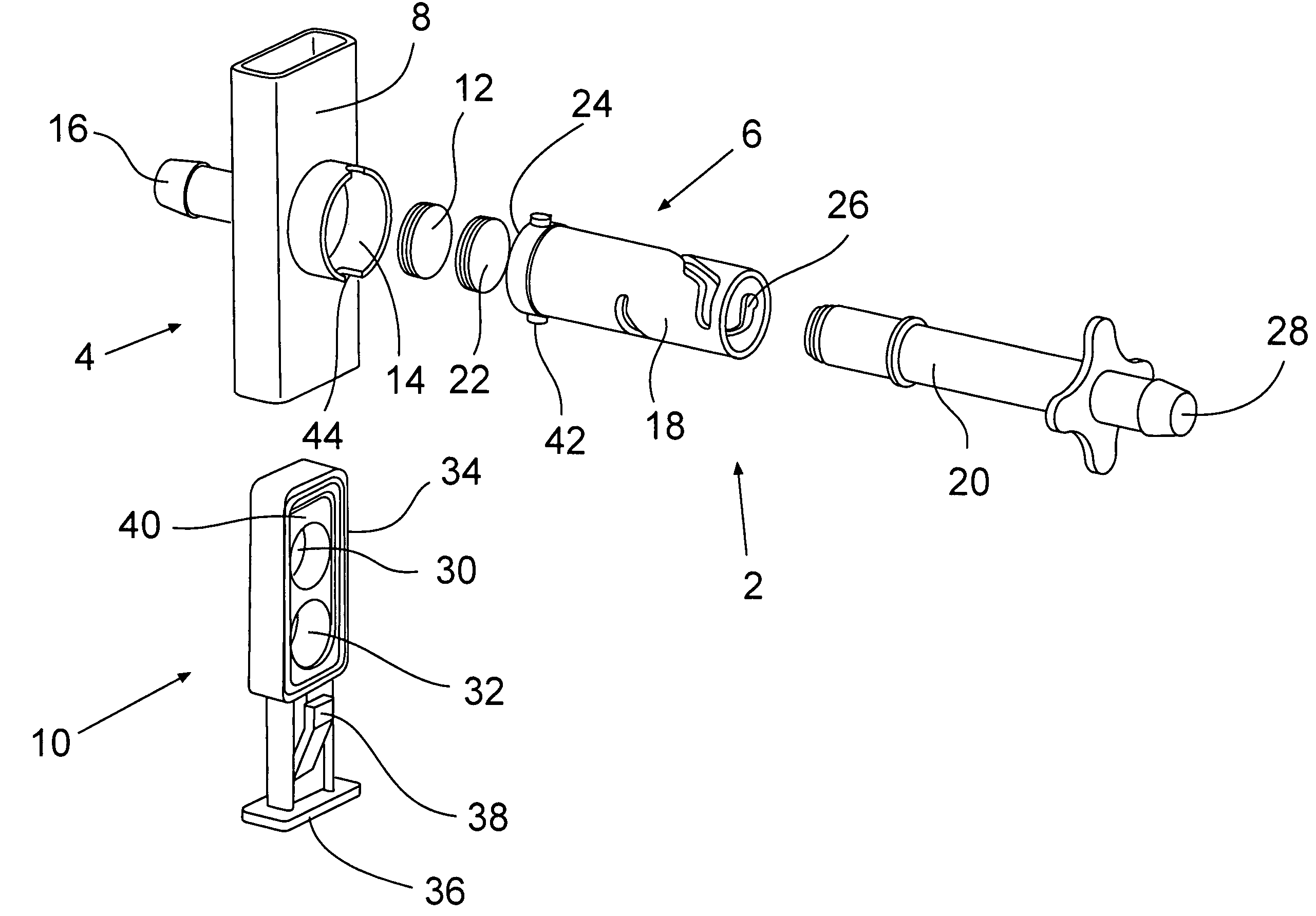
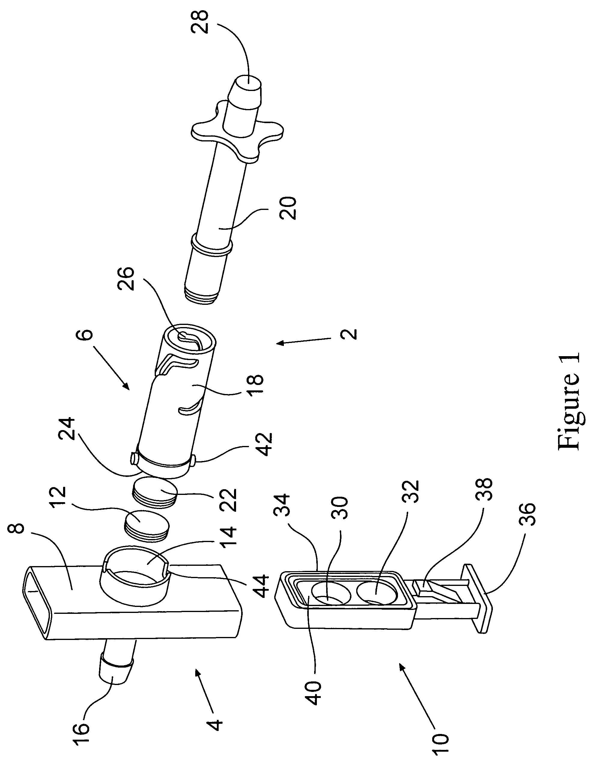
[0031]FIG. 1 shows a first embodiment of the present invention. In this embodiment one sees the two basic components a device 2 of the present invention, the connector 4 and the coupling device 6. The connector is formed of three components, a body 8, a movable port 10 and a sterile barrier plug 12. The connector in this embodiment also has a first opening 14 that is sealed by the sterile barrier plug 12 when the device is in a closed position and a second opening 16, in this embodiment in the form of a barbed connector that is connected to another sterile component (not shown).

[0032]The other basic component of the device 2 is the coupling device 6. It is formed of a body 18 a movable stem 20 contained within a portion of the body 18 and a sterile barrier plug 22 located in a first opening 24 of the coupling device. The stem 20 is contained within the second opening 26 of the coupling body. The stem 20 also has an opening 28 extending outwardly from the second opening 26 of the cou...


PUM


Abstract

A sterile to sterile connection device comprising a connector and one or more coupling devices. The connector has body portion which has two openings sealed from the environment so as to form a sterile environment within the connector. At least one of the openings being sealed from the environment by a sterile barrier plug. The connector also has a port capable movement within the body of the connector to at least an open and a closed position. The coupling device is formed of a body having two openings and a stem having a bore through at least a portion of the stem. The stem is contained within the body and capable of moving at least linearly through the body between a first and second stem position. One of the openings of the stem is sealed from the environment by a sterile barrier plug and the other is sealed to a presterilized component. The coupling device opening containing the sterile barrier plug is attached to either the inlet or outlet of the connector.

Description

[0001]The present invention relates to a connector for establishing a sterile to sterile connection. More particularly, it relates to a connector for establishing a disposable sterile to sterile connector for use in the medical, pharmaceutical and biopharmaceutical industry.BACKGROUND OF THE INVENTION[0002]In the pharmaceutical, biotechnology and even food, beverage and cosmetics industries, it is often desired to provide a processing system that is capable of handling fluids in a sterile manner. This is designed to prevent unwanted, often dangerous organisms, such as bacteria as well as environmental contaminants, such as dust, dirt and the like from entering into the process stream and / or end product. It would be desirable to have a completely sealed system but this is not always possible with the processes that take place in production.[0003]There is a need for the introduction or removal of materials from the process stream in order to add components of the product, such as medi...

Claims


Application Information

Patent Timeline
Patent Type & Authority Patents(United States)
IPC IPC(8): A61M1/00F16L37/28A61B19/00A61M39/02A61M1/16A61M39/14A61M39/18A61M39/22F16L29/00
CPCA61M39/14A61M39/22F16L29/007A61M39/18F16L2201/44Y10S604/905G01N1/2035G01N2001/205G01N2001/2071Y10T137/87925
Inventor ALMASIAN, JOSEPH M.BELONGIA, BRETT M.LENTINE, FRANKMORRISSEY, MARTINNAUSEDA, CURTISNGUYEN, CHAUPROULX, STEPHENRENGANATH, NAREN
Owner MILLIPORE CORP
Why Eureka
Try Eureka