Transconnector for coupling spinal rods

a technology of connecting rods and spinal cords, applied in the field of connecting rods, can solve the problems of bending in either of the rods, adversely affecting the fixation of the spine, clinical outcome, and bending can also adversely affect the mechanical properties of the rods, and achieve the effect of preventing uncoupling

Inactive Publication Date: 2006-11-21
SYNTHES USA
View PDF108 Cites 107 Cited by
  • Summary
  • Abstract
  • Description
  • Claims
  • Application Information

AI Technical Summary

Benefits of technology

[0008]The present invention relates to a transconnector for coupling first and second elongate spinal fixation elements that have different three dimensional orientations. The transconnector includes a male member, a female member and a locking member and can be made of any suitable material such as titanium, a titanium alloy, or stainless steel. The male member comprises a body with lateral and medial ends, a linking element associated with the lateral end and being configured and dimensioned to receive one of the fixation elements, and a projection on the medial end. The projection includes a body with a recess defined by lateral and medial walls. The female member comprises a body with lat...

Problems solved by technology

However, any bending in either of the rods can adversely affect the fixation to the spine and comprise clinical outcome.
Furthermore, the bending can also adversely affect the mechanical properties of the rods.
As is the case with bending of the rods, the mechanical properties of the transconnector could be compromised.
However, most are multi-piece systems that can be difficult to assemble and use in the surgical environment.
However, accid...

Method used


Image

  • Transconnector for coupling spinal rods
  • Transconnector for coupling spinal rods
  • Transconnector for coupling spinal rods

Examples


Embodiment Construction

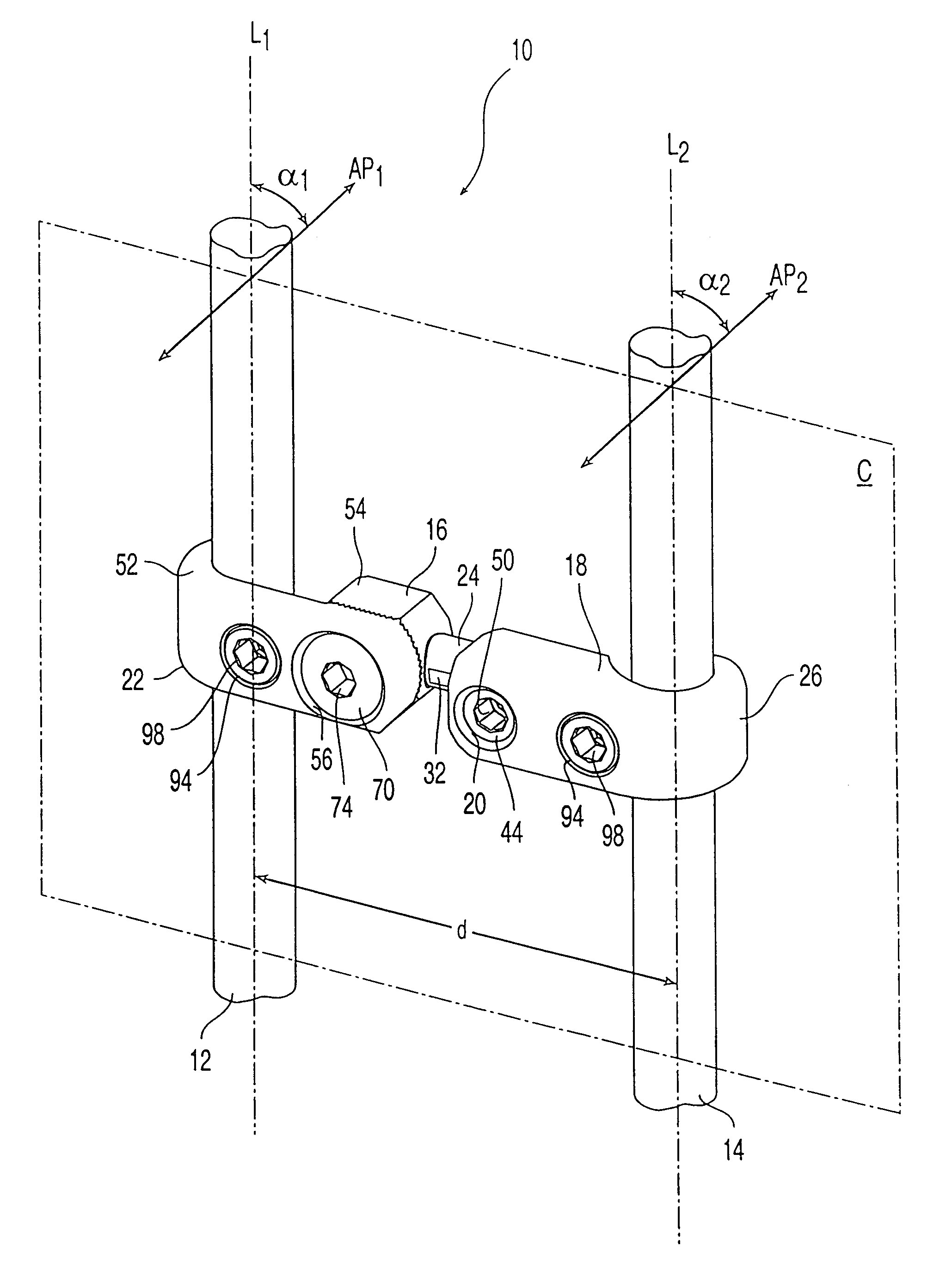
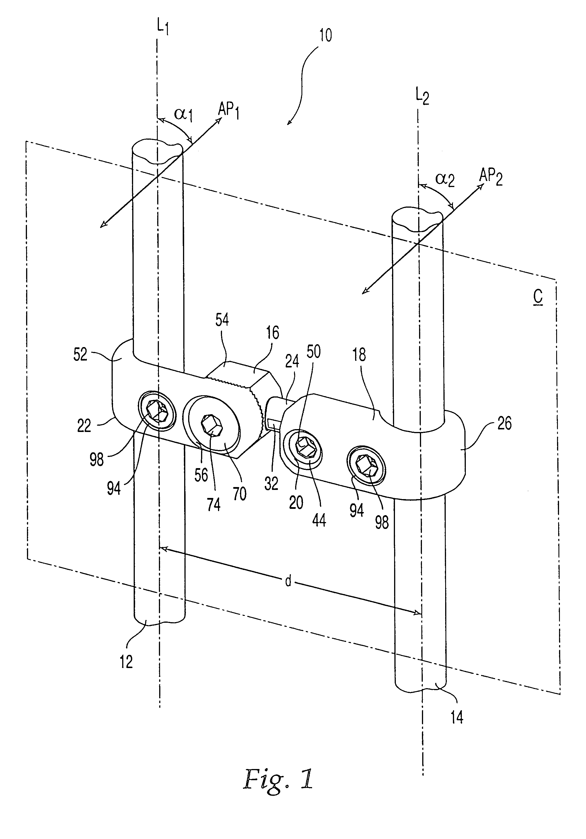
[0025]FIG. 1 shows a transconnector 10 according to the present invention for coupling a first elongate spinal fixation element 12 to a second elongate spinal fixation element 14. Transconnector 10 can be made of any suitable material typically used in orthopaedic applications such as titanium, titanium alloy, or stainless steel. If transconnector 10 is made of a metallic material, preferably it is the same metallic material used for fixation elements 12, 14 to avoid galvanic (mixed-metal) corrosion. First and second fixation elements 12, 14 can be cylindrical rods, rectangular bars, plates, or any other device suitable for spinal fusion. In use, first fixation element 12 extends along one side of the vertebral column and second fixation element 14 extends along the other side of the vertebral column. A wide variety of attachment devices such as hooks, screws, and clamps, can be used to attach first and second fixation elements 12, 14 to the spine.

[0026]Transconnector 10 includes a ...


PUM


Abstract

The present invention is directed to a transconnector for coupling first and second spinal fixation rods or other elongate fixation elements. The transconnector includes a male member, a female member, and a locking member. The male member has a body with a linking element (such as a hook) associated with the lateral end for receiving one of the fixation elements, and a projection on the medial end. The projection includes a recess defined by lateral and medial walls. The female member has a body with a linking element associated with the lateral end for receiving the other fixation element, and a cavity with an opening on the medial end for receiving a portion of the male member projection. The locking member secures the position and orientation of the male member projection portion in the cavity in order to accommodate different separation distances and orientations between the first and second fixation elements. The locking member cooperates with the medial wall of the recess of the projection to prevent uncoupling of the male and female members. The male member may be made as a two component assembly in which the two components can rotate relative to one another for accommodating rod convergence or divergence.

Description

CROSS-REFERENCE TO RELATED APPLICATION[0001]The present application is a continuation of U.S. patent application Ser. No. 09 / 927,350, filed Aug. 13, 2001 now U.S. Pat. No. 6,736,817 B1, which is a continuation of U.S. patent application Ser. No. 09 / 466,725, filed Dec. 17, 1999, now U.S. Pat. No. 6,283,967 B1, the entire content of which are expressly incorporated herein by reference thereto.FIELD OF THE INVENTION[0002]The present invention relates to a device for spinal fixation, and in particular to a transconnector for coupling spinal rods, plates, or other elongate members.BACKGROUND OF THE INVENTION[0003]It is often necessary to surgically treat spinal disorders such as scoliosis. Numerous systems for use in spinal correction and fixation have been disclosed. These systems usually include a pair of elongate members, typically either rods or plates, placed along the vertebral column. For the sake of simplicity, the term “rod” is used throughout to refer to any elongate member. Ea...

Claims


Application Information

Patent Timeline
IPC IPC(8): A61B17/56A61B17/58A61B17/70
CPCA61B17/7052
Inventor TROXELL, THOMAS N.KUMAR, G. KRISDAVIS, BARCLAY R.RUNCO, THOMAS J.
Owner SYNTHES USA
Why Eureka
Try Eureka