Indirectly heated cathode ion source

a technology of indirect heating and ion sources, which is applied in the field of indirect heating cathodes of ion sources, can solve the problems of large diameter of tubes, increased size and complexity of the structure, and deformation or failure of direct heating cathodes in the corrosive environment of arc chambers

Inactive Publication Date: 2006-11-21
VARIAN SEMICON EQUIP ASSOC INC
View PDF26 Cites 62 Cited by
  • Summary
  • Abstract
  • Description
  • Claims
  • Application Information

AI Technical Summary

Benefits of technology

[0017]According to a further aspect of the invention, an indirectly heated cathode ion source is provided. The indirectly heated cathode ion source comprises an arc chamber housing defining an arc chamber, an indirectly heated cathode positioned within the arc chamber, a filament positioned outside the arc chamber for heating the indirectly heated cathode, wherein the indirectly heated cathode provides electrons for generating a plasma within the arc chamber, and means for inhibiting escape of the electrons and the plasma from a region outside the arc chamber in proximity to the filament...

Problems solved by technology

Such directly heated cathodes typically constitute a relatively small diameter wire filament and therefore degrade or fail in the corrosive environment of the arc chamber in a relatively short time.
As a result, the lifetime of the directly heated cathode ion source is limited.
The large diameter of the tube increases the size and complexity of the structure used to clamp and connect to the c...

Method used


Image

  • Indirectly heated cathode ion source
  • Indirectly heated cathode ion source
  • Indirectly heated cathode ion source

Examples


Embodiment Construction

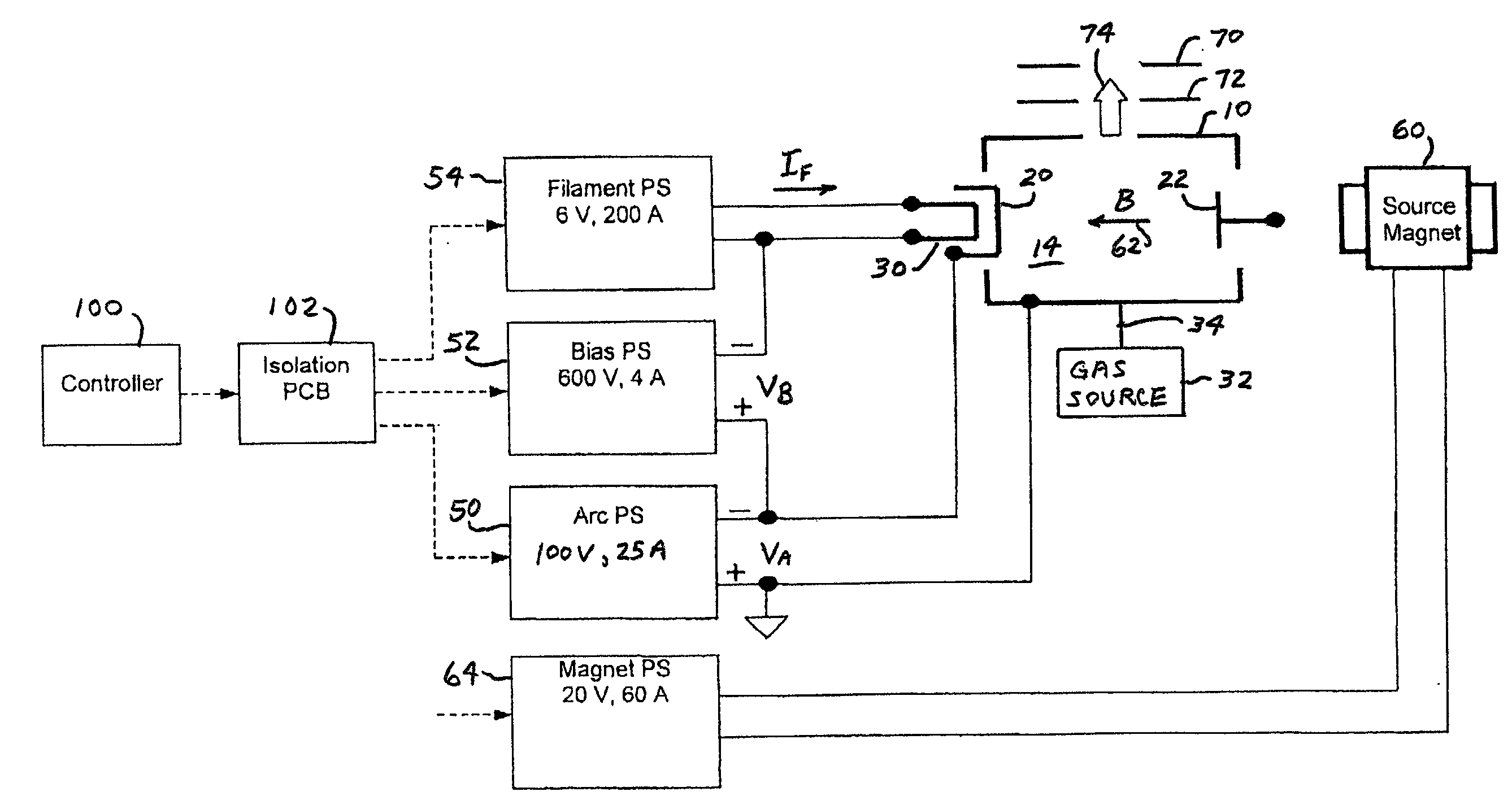
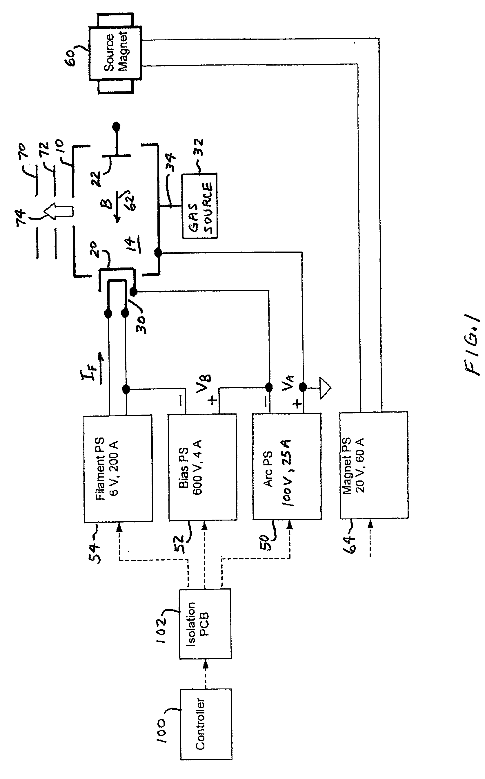
[0032]An indirectly heated cathode ion source in accordance with an embodiment of the invention is shown in FIG. 1. An arc chamber housing 10 having an extraction aperture 12 defines an arc chamber 14. A cathode 20 and a repeller electrode 22 are positioned within arc chamber 14. A filament 30, positioned outside arc chamber 14 in close proximity to cathode 20, produces heating of cathode 20.

[0033]A gas to be ionized is provided from a gas source 32 to arc chamber 14 through a gas inlet 34. In another configuration, not shown, arc chamber 14 may be coupled to a vaporizer which vaporizes a material to be ionized in arc chamber 14.

[0034]An arc power supply 50 has a positive terminal connected to arc chamber housing 10 and a negative terminal connected to cathode 20. Repeller electrode 22 can be floating as shown in FIG. 1 or can be connected to the negative terminal of arc power supply 50. Arc power supply 50 may have a rating of 100 volts at 25 amperes and may operate at about 70 vol...


PUM


Abstract

An indirectly heated cathode ion source includes an arc chamber housing that defines an arc chamber, an indirectly heated cathode and a filament for heating the cathode. The cathode may include an emitting portion having a front surface, a rear surface and a periphery, a support rod attached to the rear surface of the emitting portion, and a skirt extending from the periphery of the emitting portion. A cathode assembly may include the cathode, a filament and a clamp assembly for mounting the cathode and the filament in a fixed spatial relationship and for conducting electrical energy to the cathode and the filament. The filament is positioned in a cavity defined by the emitting portion and the skirt of the cathode. The ion source may include a shield for inhibiting escape of electrons and plasma from a region outside the arc chamber in proximity to the filament and the cathode.

Description

FIELD OF THE INVENTION[0001]This invention relates to ion sources that are suitable for use in ion implanters and, more particularly, to ion sources having indirectly heated cathodes.BACKGROUND OF THE INVENTION[0002]An ion source is a critical component of an ion implanter. The ion source generates an ion beam which passes through the beamline of the ion implanter and is delivered to a semiconductor wafer. The ion source is required to generate a stable, well-defined beam for a variety of different ion species and extraction voltages. In a semiconductor production facility, the ion implanter, including the ion source, is required to operate for extended periods without the need for maintenance or repair.[0003]Ion implanters have conventionally used ion sources with directly heated cathodes, wherein a filament for emitting electrons is mounted in the arc chamber of the ion source and is exposed to the highly corrosive plasma in the arc chamber. Such directly heated cathodes typically...

Claims


Application Information

Patent Timeline
IPC IPC(8): H01J7/24H01J27/02H01J27/04H01J27/08H01J37/08H01J37/317
CPCH01J27/022H01J27/08H01J2237/08H01J2237/31701H01J1/20H01J1/26H01J27/02
Inventor MACIEJOWSKI, PETER E.OLSON, JOSEPH C.CHANG, SHENGWUPEDERSEN, BJORN O.KLOS, JR., LEO V.DISTASO, DANIELBERGERON, CURT D.
Owner VARIAN SEMICON EQUIP ASSOC INC
Why Eureka
Try Eureka