Eureka AIR delivers breakthrough ideas for toughest innovation challenges, trusted by R&D personnel around the world.

Apparatus and method for measuring inflation pressure

a technology of inflation pressure and apparatus, applied in the direction of tyre measurement, tyre parts, structural/machine measurement, etc., can solve the problems of system noise, inconvenient exploitation of the whole apparatus, complicated whole gauge, etc., and achieve the effect of reducing the frequency of broadcasting

Inactive Publication Date: 2006-11-28
MELNIKOV VALENTINA
View PDF6 Cites 0 Cited by
  • Summary
  • Abstract
  • Description
  • Claims
  • Application Information

AI Technical Summary

Benefits of technology

[0017]The other object of the present invention is to provide for a new and improved device, which has simple, modular construction, which has small size, is inexpensive and does not require adaptation of existing tire for mounting thereon of the pressure sensing member.

Problems solved by technology

The disadvantage of this system is associated with the necessity to provide transducer means with a dedicated source of energy, which renders the whole gauge complicate, expensive and less reliable.
Furthermore, such system creates noise, since the transducer means broadcasts the radio signal permanently.
This requirement renders the whole apparatus inconvenient in exploitation, especially when it is used in conditions of bad weather, limited visibility or in darkness.
Besides such pressure sensing member cannot be attached to any standard valve of a vehicle tire without introducing changes in the standard wheel design.
The above-described pressure sensing member has relatively complicated construction, which includes pressure cell, tuning capacitor, pressure cell and three separate printed circuit boards.
This renders the whole device relative expensive and less reliable.
However, in the applications, which require measuring inflation pressure in a tire of a relatively small or a medium-sized vehicle, e.g. private car, autobus, truck, tractor etc., this apparatus in fact would be inferior and even disadvantageous in comparison with traditional, commonly used pneumatic pressure gauge.

Method used


Image

  • Apparatus and method for measuring inflation pressure
  • Apparatus and method for measuring inflation pressure
  • Apparatus and method for measuring inflation pressure

Examples


Embodiment Construction

[0037]The working principle of the present invention is based on transmitting of energy from an external autonomous member to a pressure sensing member, which is located within inflated resilient vessel. The pressure sensing member is exposed to the inflation pressure and is capable upon energizing to sense the inflation pressure within the vessel and to generate a signal, depending on this pressure. This signal is then transmitted by the pressure sensing member to the external member and is processed in the external member to derive the value of the inflation pressure.

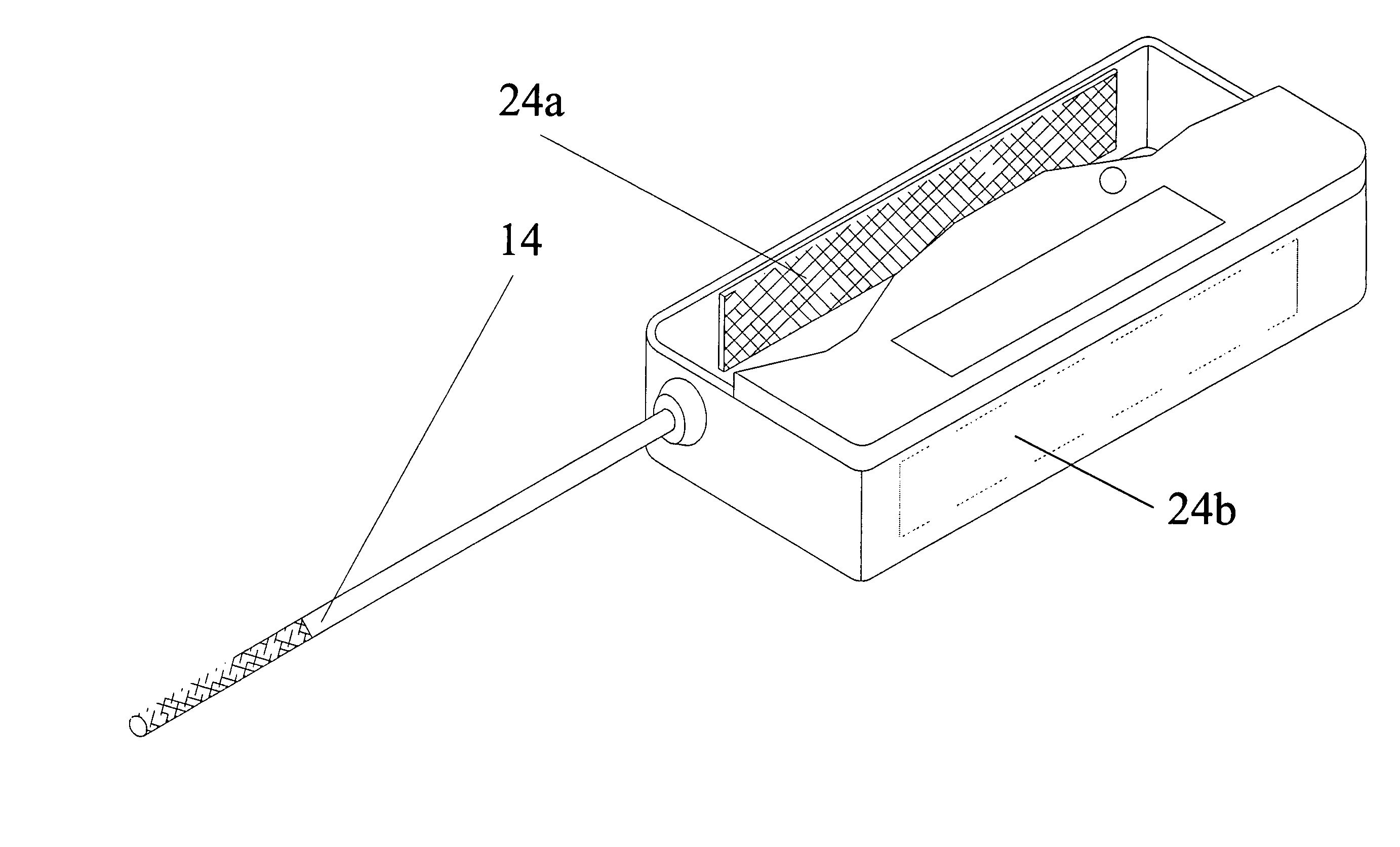
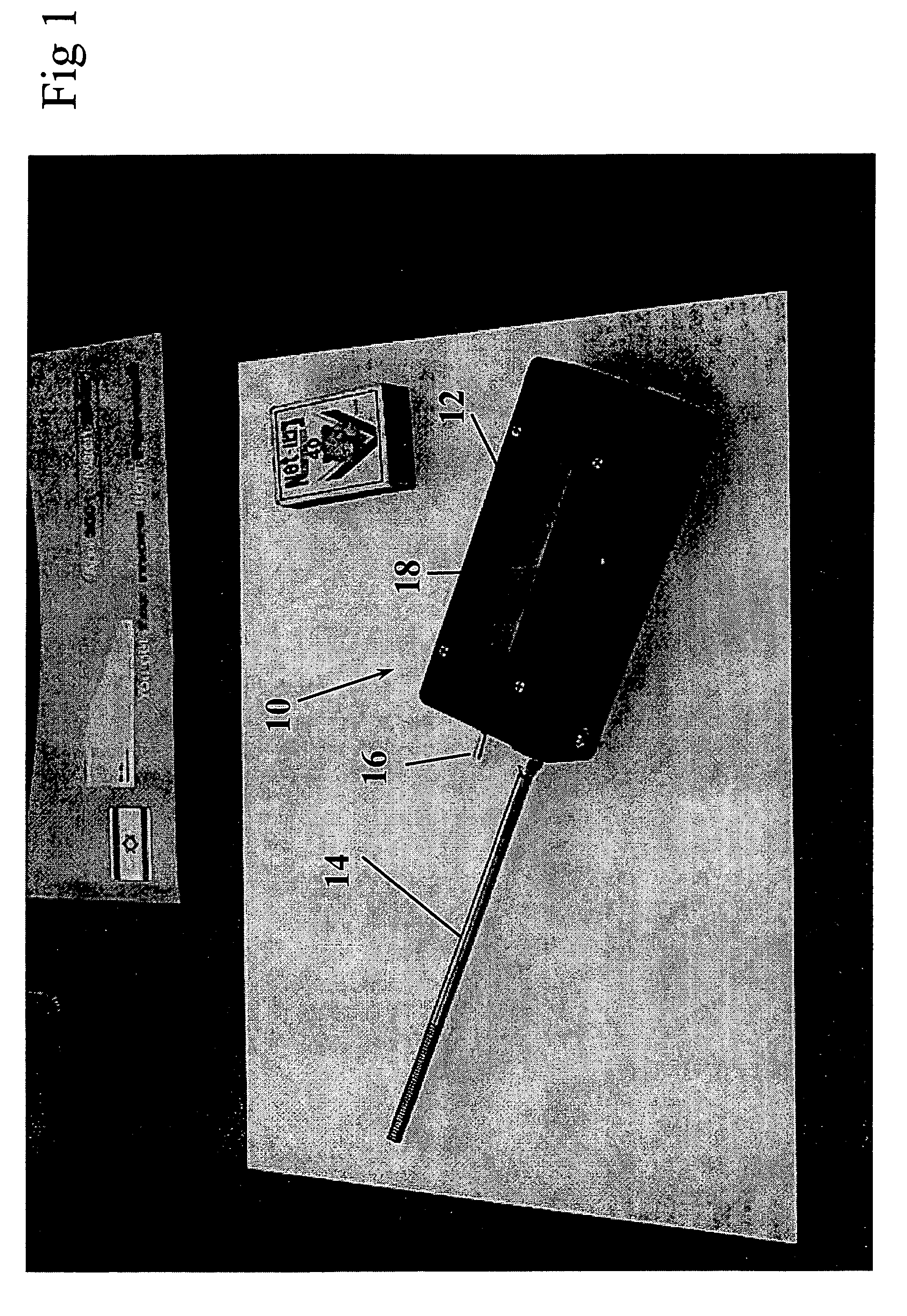
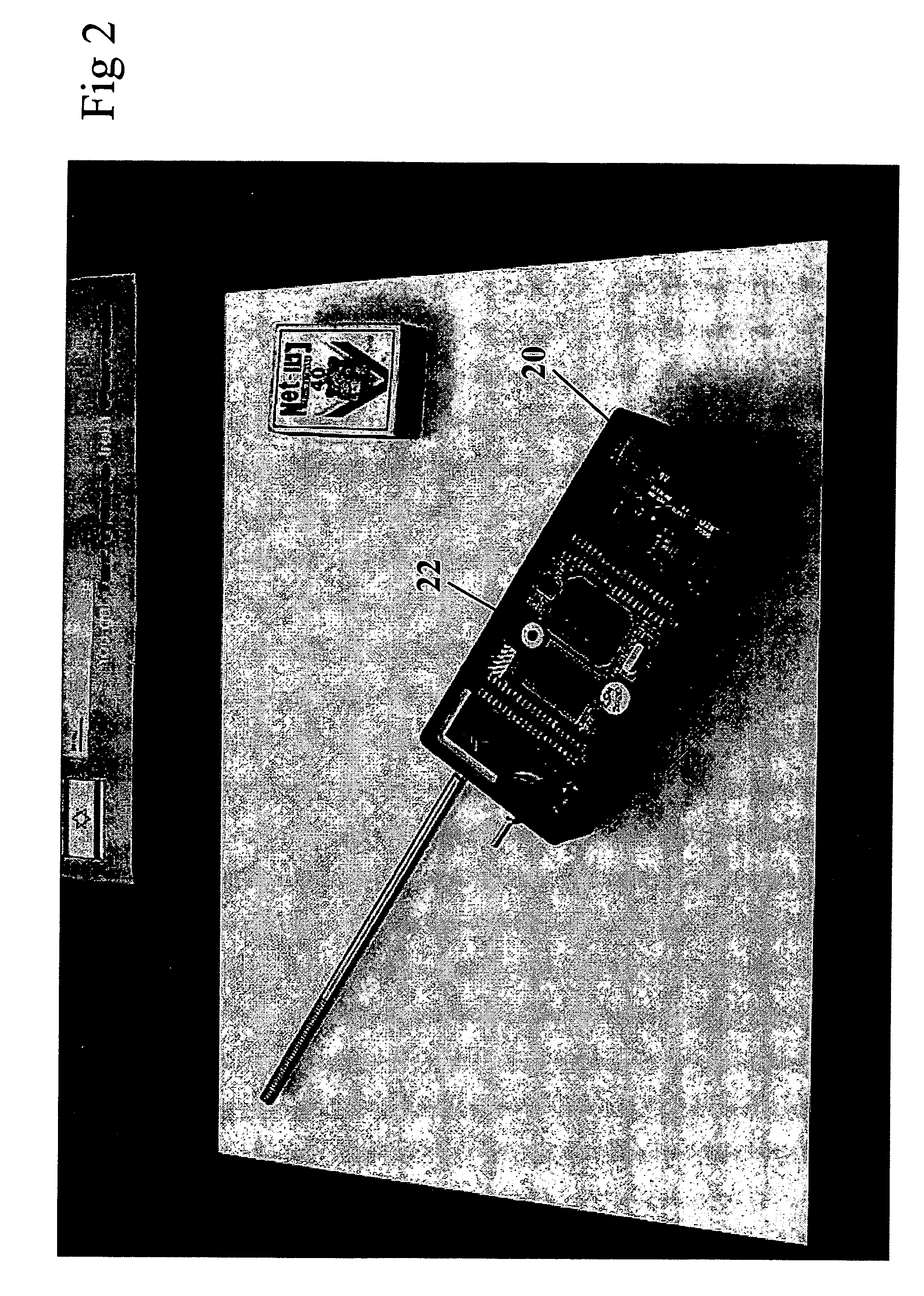
[0038]Accordingly, the first embodiment of the present invention concerns an apparatus which comprises two main components, i.e. an external member and a pressure-sensing member. These members are respectively presented in FIGS. 1–3 and in FIG. 7.

[0039]Referring now to FIG. 1 the external member 10 is seen, which is configured as a box having housing 12, in which are received various electrical and electronic componen...


PUM


Abstract

An apparatus for measuring inflation pressure of a resilient-walled vessel, e.g. of a vehicle tire associated with an inflation valve and with a rim. The apparatus has an external, portable member and a pressure sensing member, which is separate from the portable member and is located within the tire so as to be exposed to the inflation pressure. The portable member is capable of generating and transmitting energy to the pressure sensing member and in response to receive and to process a pressure signal, which depends on the inflation pressure and upon processing of the pressure signal to derive therefrom an inflation pressure value. The pressure sensing member is capable, upon receiving energy from the portable member, to generate the pressure signal and to transmit it to the portable member. The portable member has a probe that creates an electrical contact between the portable member and the pressure sensing member upon establishing physical contact between the probe and the valve. The pressure sensing member creates n electrical contact with the rim and with the valve.

Description

[0001]This application is a national phase of PCT / IL2003 / 000432 (WO2004 / 002757) filed May 25, 2003, which claims the benefit of Provisional Application No. 60 / 391,237, filed Jun. 26, 2002.FIELD OF THE INVENTION[0002]The present invention relates to measuring of internal pressure within a resilient-walled vessel. More particularly the invention refers to apparatus comprising portable handheld probe member suitable for measuring of internal pressure of a pneumatically inflated tire of a vehicle and to a measuring method, implemented in this apparatus.BACKGROUND OF THE INVENTION[0003]There are known various methods and devices, which have been devised for measuring of internal pressure within a pneumatically inflated tire of a vehicle. Those means can be divided into various groups according to the principle of their operation:[0004]The first group includes monitoring systems mounted on a vehicle wheel and capable to detect and indicate the pressure within a tire when the vehicle moves...

Claims


Application Information

Patent Timeline
Patent Type & Authority Patents(United States)
IPC IPC(8): B60C23/02B60C23/04
CPCB60C23/0432B60C23/0479
Inventor NOVIKOV, MARKGELLER, BENJAMIN
Owner MELNIKOV VALENTINA
Why Eureka
Eureka Blog
Learn More