Single row twine box

a twine box and single row technology, applied in the field of agricultural balers, can solve the problems of need and possible difficulty in accessing twine balls, and achieve the effects of preserving the overall length of the box, convenient access to twine balls, and compact manufacturing

Active Publication Date: 2006-11-28
DEERE & CO
View PDF7 Cites 10 Cited by
  • Summary
  • Abstract
  • Description
  • Claims
  • Application Information

AI Technical Summary

Benefits of technology

[0006]By locating all the balls of twine on a single row and by keeping the twine ball compartments open, the twine balls (within a twine ball group) can be moved to another location within the twine ball group, without cutting and retying the twine. This aids the operator in arranging and loading twine. A twine ball group is two or more balls of twine tied together to feed a single twine knotter on the baler. Twine balls can be placed all in a single row or staggered to conserve the overall length of the box.
[0007]One of the difficulties of placing the twine balls next to each other on the same level is the need and possible difficulty of accessing the twine balls that are furthest from the operator and behind the other balls of twine (when staggered). The twine balls in this concept are not compartmentalized during service. To allow the operator access to these twine balls, partitions which define the twine ball compartment within the twine box have traditionally been placed on the back wall of the twine box. By eliminating partitions that compartmentalize the twine balls and instead utilizing twine ball separators, the inside of the twine box can be free of structure that impedes the access to the twine balls that are located along the back wall of the twine box.
[0008]Twine ball separators mounted on the twine box door engage the balls of twine when closed to ensure the balls are located correctly and do not fall over. These separators disengage from the balls when the door is opened, allowing easy access and relocation of twine balls.
[0009]The present invention thus provides easier access to twine balls for loading and unloading as well as flexibility on rearranging twine balls within a specific group. Such a configuration can also be manufactured more compactly and at a lower cost.

Problems solved by technology

One of the difficulties of placing the twine balls next to each other on the same level is the need and possible difficulty of accessing the twine balls that are furthest from the operator and behind the other balls of twine (when staggered).

Method used


Image

  • Single row twine box
  • Single row twine box
  • Single row twine box

Examples


Embodiment Construction

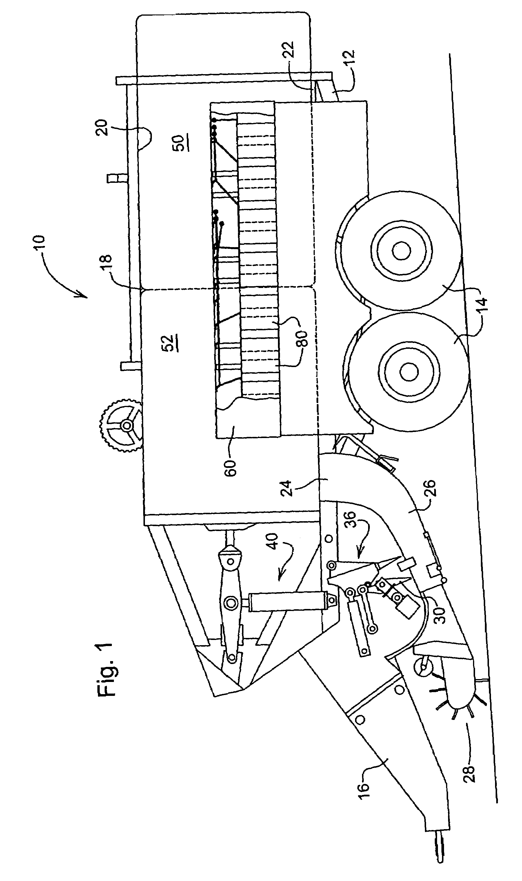
[0020]With reference now to the drawings it can be seen that a large parallelepiped agricultural baler is designated generally by the numeral 10. The baler 10 includes a frame 12 supported on a tandem set of ground wheels 14. A tongue 16 is fixed to and extends forwardly from the frame 12 and is adapted for being attached to a prime mover, such as an agricultural tractor (not shown) equipped with a power take-off shaft for supplying power for driving various driven components of the baler. A baling chamber 18 of rectangular cross section is defined in part by upper and lower walls 20 and 22, respectively, with the lower wall 22 being provided with a crop inlet 24 to which is attached a curved in-feed duct 26 which serves as a pre-compression chamber. A crop pick-up and center-feed auger assembly 28 is provided ahead of the duct for picking up a windrow of crop from the ground and delivering it to a packer fork assembly 30 which acts to pack crop into the duct 26 until a charge of a ...


PUM


Abstract

A twine box is provided for an agricultural baler. The twine box permits ready access to twine balls housed therein because all twine balls are located on a single row or tier. The twine balls are not compartmentalized and thus relocation of twine balls within twine ball groups is facilitated. Twine ball separators are employed to secure, locate and separate twine balls when the baler is operating. The twine ball separators may serve to maintain twine balls in a staggered configuration whereby it is possible to house a greater number of twine balls in a given space. The twine ball separators do not interfere with the movement of twine balls within the twine box during reloading of twine. The single row twine box allows the baler operator to access the twine balls from the ground and permits moving of twine balls without the need to cut and retie twine.

Description

FIELD OF THE INVENTION[0001]The present invention relates generally to agricultural balers. More particularly, the present invention relates to such balers that form discrete bales of crop material and wherein twine is used for wrapping the bales to maintain bale shape and structural integrity after being formed in the baling chamber. Specifically, the present invention relates to an improved twine box for holding, storing and dispensing twine.BACKGROUND OF THE INVENTION[0002]Agricultural balers commonly have machine configurations that cause the location of the twine box, usually a double row twine box, to be situated such that access by the operator from the ground is limited, especially the top row of twine balls. This is more apparent on larger size balers, and sometimes requires the operator to stand on an elevated platform such as a truck bed or step ladder to load twine. In order to carry enough twine capacity for larger square balers, manufacturers have previously chosen mul...

Claims


Application Information

Patent Timeline
Patent Type & Authority Patents(United States)
IPC IPC(8): B65B13/18
CPCA01F15/12Y10S100/912
Inventor ROTOLE, DAVID VINCENTSUMSION, STANLEY RAY
Owner DEERE & CO
Why Eureka
Try Eureka