Coolant system with thermal energy storage and method of operating same

a technology of cooling system and thermal energy storage, which is applied in the direction of engine cooling apparatus, machines/engines, mechanical equipment, etc., can solve the problems of cold air being exhausted into the passenger compartment, thermal energy carried by the cooling system will soon dissipate into the environment, and the supply of thermal energy in the cooling system often lags behind the demand for warmer cabin temperatures

Inactive Publication Date: 2006-11-28
MODINE MFG CO
View PDF18 Cites 25 Cited by
  • Summary
  • Abstract
  • Description
  • Claims
  • Application Information

AI Technical Summary

Problems solved by technology

However, the supply of thermal energy in the coolant system often lags behind the demand for warmer cabin temperatures.
In particular, if the engine is turned off in the cold weather, the thermal energy carried by the coolant system will soon dissipate into the environment.
If the engine is then restarted and the heater turned on, cold air may actually be exhausted into the passenger compartment because the coolant is not warm enough to sufficiently heat the air stream passing through the secondary heat exchanger.
Most people find this to be uncomfortable and undesirable.
There are drawbacks, however, to adding sensible heat batteries to conventional coolant systems.
Because coolant can only carry so much thermal energy in the form of sensible heat, the conventional sensible heat battery is quite large.
Furthermore, the weight of the additional coolant needed to fill the heat battery (over that required to fill the coolant system) can degrade such weight-dependent performance characteristics as fuel economy.
Moreover, heat batteries can be expensive to install and maintain.
However, it is believed that problems may arise when the coolant in the heat battery is pumped back into the coolant system.
Consequently, with this heat battery there will always be some coolant which cannot be recovered for use in the coolant system.

Method used


Image

  • Coolant system with thermal energy storage and method of operating same
  • Coolant system with thermal energy storage and method of operating same
  • Coolant system with thermal energy storage and method of operating same

Examples


Embodiment Construction

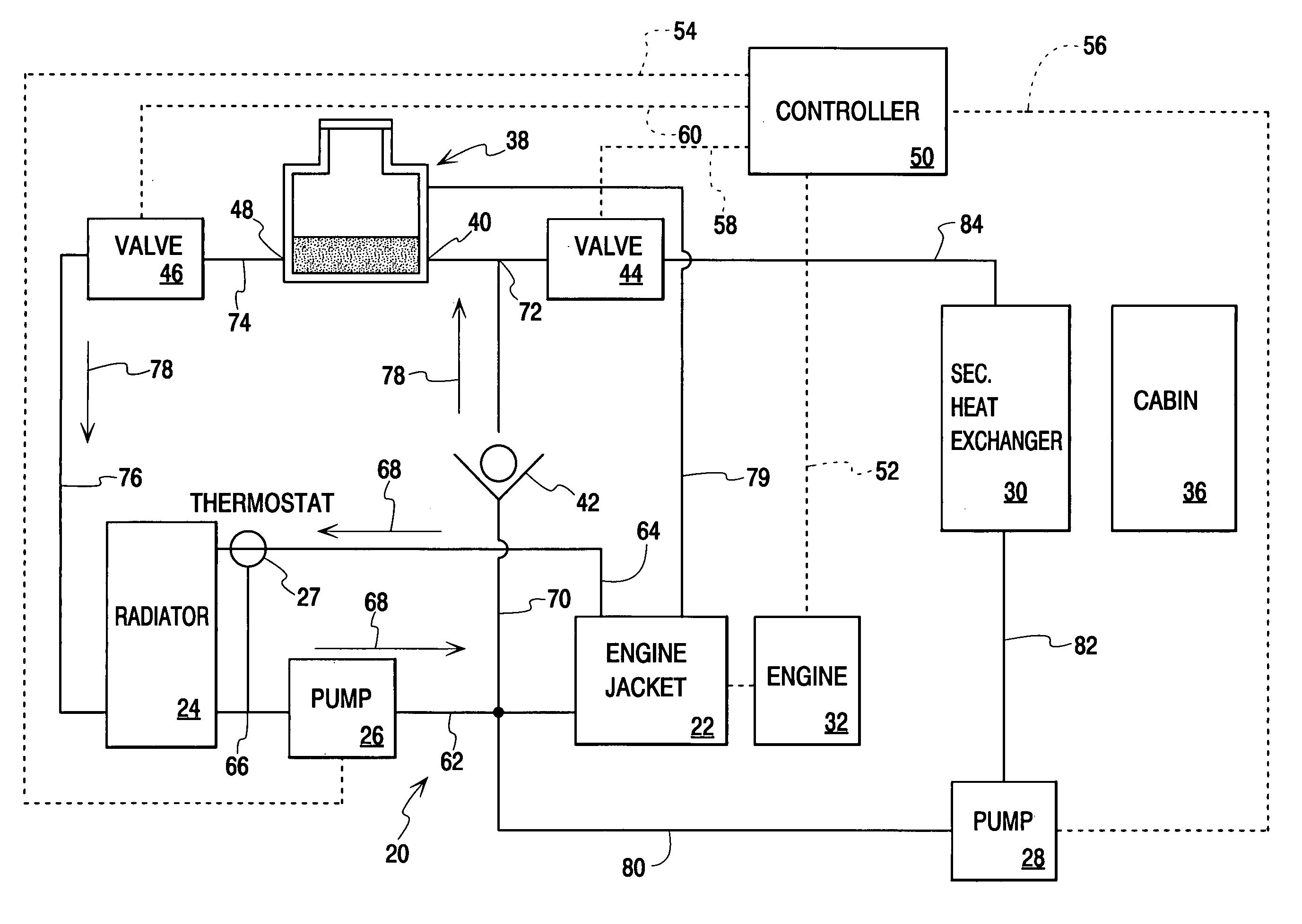
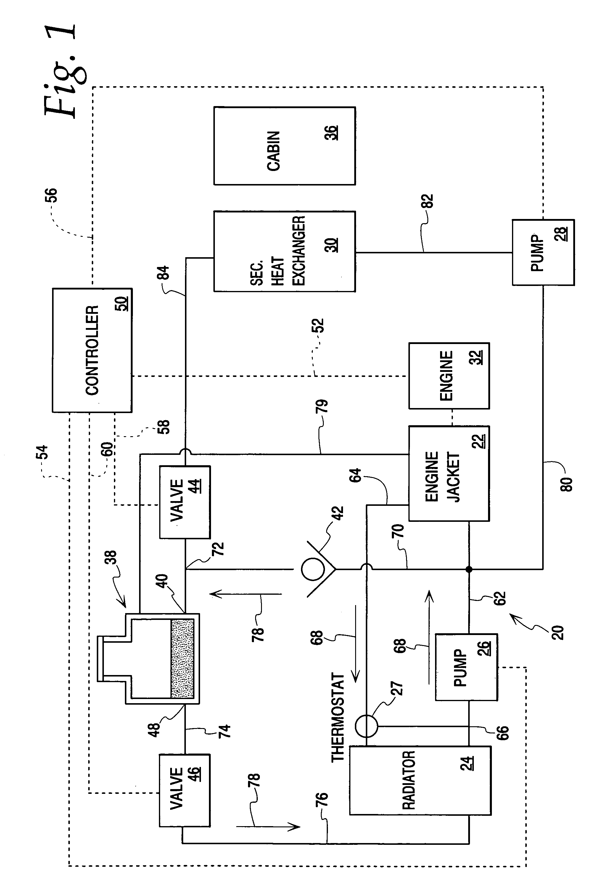
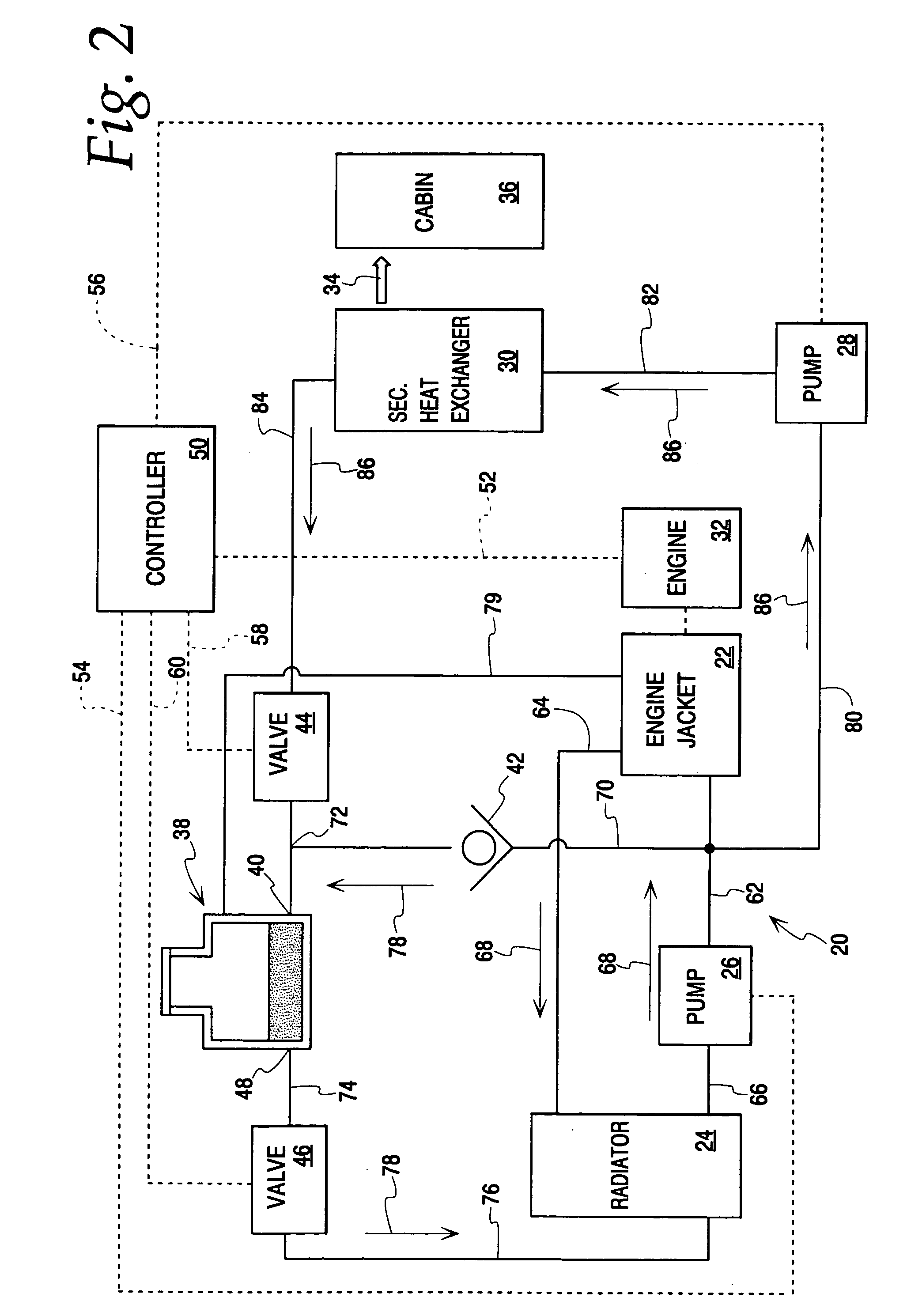
[0028]FIGS. 1–4 illustrate one embodiment of a coolant system with thermal energy storage according to the present invention, while FIGS. 5–7 illustrate another embodiment of the present invention. In both systems, coolant is removed from the coolant system for storage in an insulated tank during periods of engine inactivity and is returned to the coolant system prior to reactivation of the engine. Additionally, in both systems, a method and mechanism is provided to maximize the return of the stored coolant to the coolant system. Further, in both systems, a mechanism and a method is provided for passing heated coolant through the storage tank during engine operation to continuously warm the coolant in the tank.

[0029]Specifically, according to the first embodiment of the invention, a coolant system 20 is shown in FIG. 1. The coolant system 20 includes an engine coolant jacket 22, a radiator 24, a circulation pump 26, and a thermostat 27 to control the temperature of the coolant by by...


PUM


Abstract

A coolant system includes a heat exchange circuit capable of being in a heat exchange relationship with a heat generating component, such as an engine, to remove thermal energy from the engine and transfer the thermal energy to a coolant, and an insulated tank in fluid communication with the heat exchange circuit. The system also includes a control and associated conduits and valves for passing coolant through the heat exchange circuit and the insulated tank so as to fill the tank with a first volume of coolant in a first operational state, for passing an additional amount of coolant from the heat exchange circuit into the insulated tank so as to fill the insulated tank with a second volume of coolant which is greater than the first volume of coolant in a second operational state, and for passing the additional amount of coolant from the insulated tank to the heat exchange circuit in a third operational state. A method of operating the coolant system to store thermal energy is also provided.

Description

FIELD OF THE INVENTION[0001]The present invention relates to a coolant system with thermal energy storage and a method of operating the system to store thermal energy, and in particular to a coolant system equipped with a sensible heat battery and a method of operating the coolant system to store thermal energy in the sensible heat battery.BACKGROUND OF THE INVENTION[0002]Thermal energy storage devices can find use in many applications. For example, they can be used to preheat fuel cell coolant to heat a fuel cell stack, particularly on vehicles such as hybrid vehicles that include a fuel cell, to preheat the engine of a vehicle for rapid engine warm-up, to preheat a transmission for rapid transmission warm-up, and / or to heat a passenger compartment of a vehicle under conditions where the heat from the vehicle engine is not sufficient.[0003]One way to heat the passenger compartment of a vehicle equipped with an internal combustion engine is to redirect some of the thermal energy car...

Claims


Application Information

Patent Timeline
Patent Type & Authority Patents(United States)
IPC IPC(8): F01P11/02
CPCF01P11/20F01P2007/146F01P2011/205
Inventor ROGERS, C. JAMESZOBEL, WERNERVOSS, MARK G.
Owner MODINE MFG CO
Why Eureka
Try Eureka