
Portable pipe cutting apparatus

a cutting device and portability technology, applied in the field of portability devices, can solve the problems of unsafe operator, serious injury to operator or damage to cutting blades, and the inability of the vise to securely hold round stock, so as to reduce the risk of injury to the operator and/or damage to the cutting blade, and reduce muscle strain

Inactive Publication Date: 2006-11-28
LEBERFINGER MATTHEW +1
View PDF25 Cites 19 Cited by
  • Summary
  • Abstract
  • Description
  • Claims
  • Application Information

AI Technical Summary

Benefits of technology

"The present invention is a portable power tool that can securely hold and cut small diameter pipes and other non-flat stock. It includes an adjustable work support, a V-shaped trough, a chain and tightening device, a catch tray, support arm brackets, a mounting stand, and a power tool. The apparatus prevents movement of the pipe during cutting or other operations, reducing the risk of injury and damage to the cutting blade. It also reduces muscle strain for the operator by reducing the need for bending, squatting, and kneeling during the cutting process."

Problems solved by technology

A further shortcoming of the saw and vise arrangement is that it is unsafe for the operator.
However, the vise is unable to retain round stock securely in place.
As a result, these materials often break free of the vise, causing serious injury to the operator or damage to the cutting blade.
This occurs more frequently during the colder months, when pipe tends to be brittle.
In addition, the flat design of the vise often fails to accomplish the precise cutting that is required for pipe fitting operations.
However, the base portions of saws used in the art are only about 12 to 14 inches in length, which is inadequate for supporting large pipe, being defined herein as pipe having lengths of 15 inches or greater.
As a result, the ends of the pipe are difficult to support and frequently sag on the dirt, concrete, shale or mud surfaces.
Moreover, in order for a complete cross-section of the pipe to be cut, McKown requires that the pipe be rolled or rotated while it is being cut, posing a hazard to an operator.
The apparatus is not suitable for supporting small, round stock in a tight and secure fashion.
The support stand includes a flat surface for supporting a workpiece but does not provide means for steadily and fixedly securing round workpieces, such as pipe, and does not include an integral cutting device.

Method used


Image

  • Portable pipe cutting apparatus
  • Portable pipe cutting apparatus
  • Portable pipe cutting apparatus

Examples


Embodiment Construction

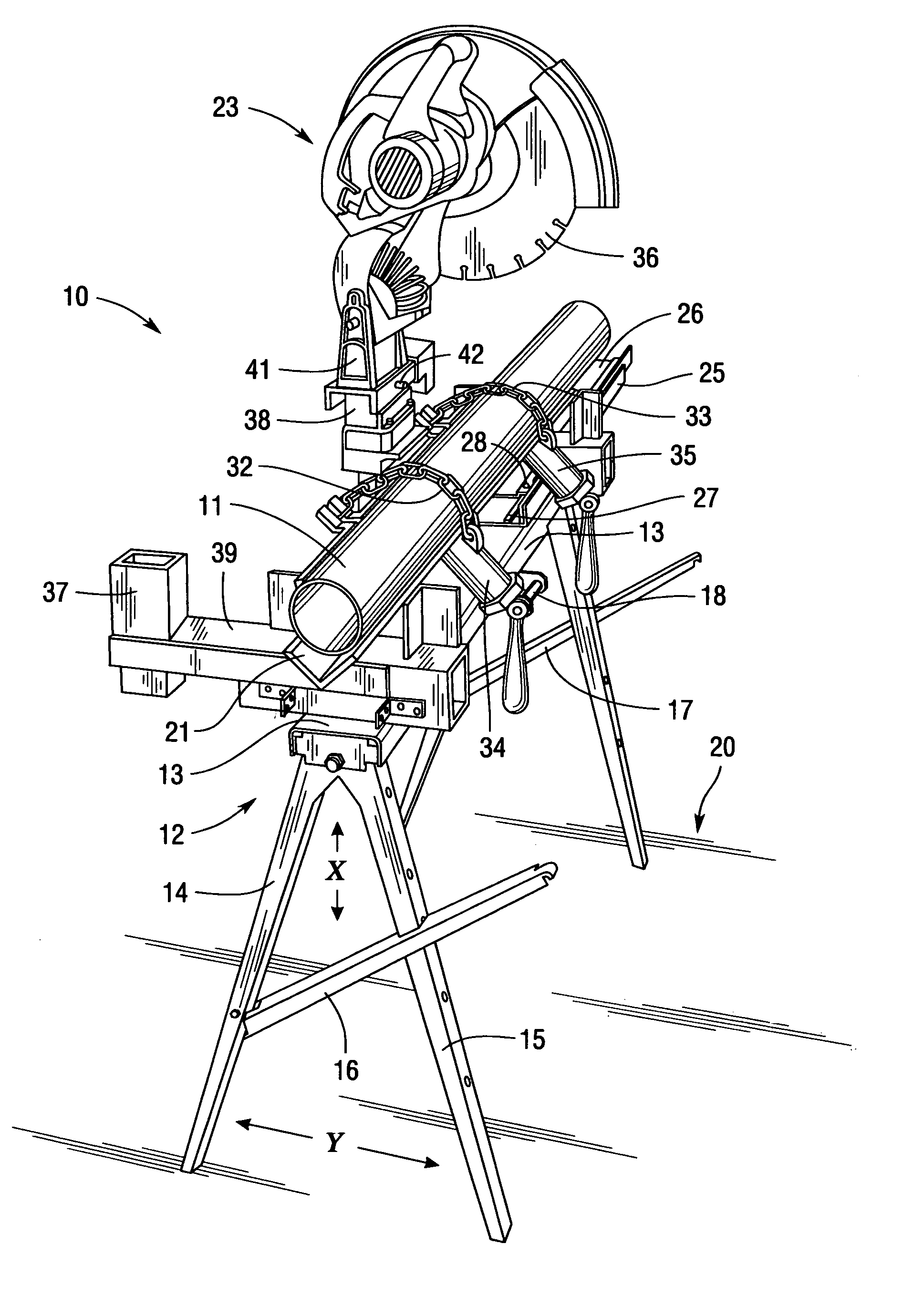
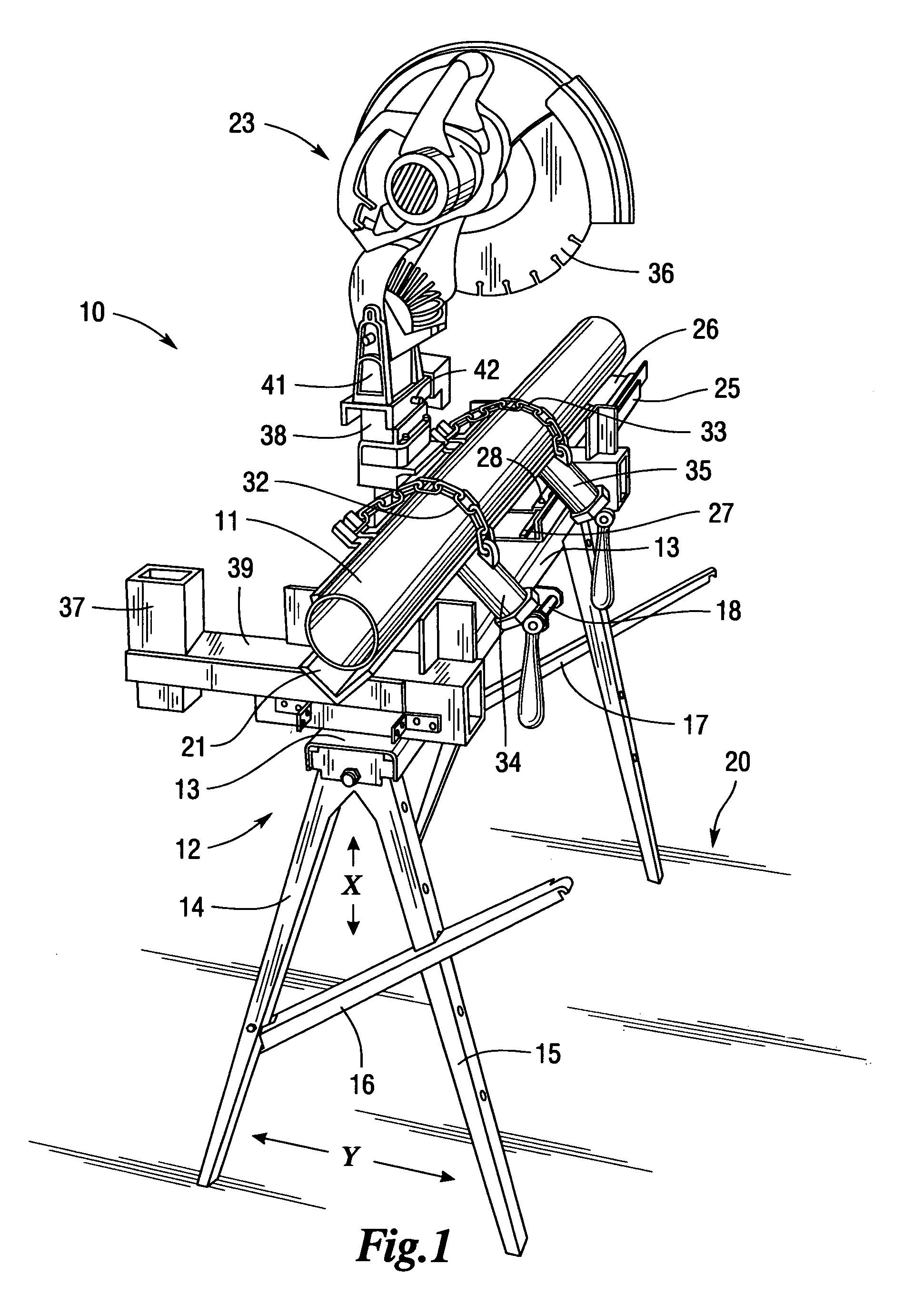
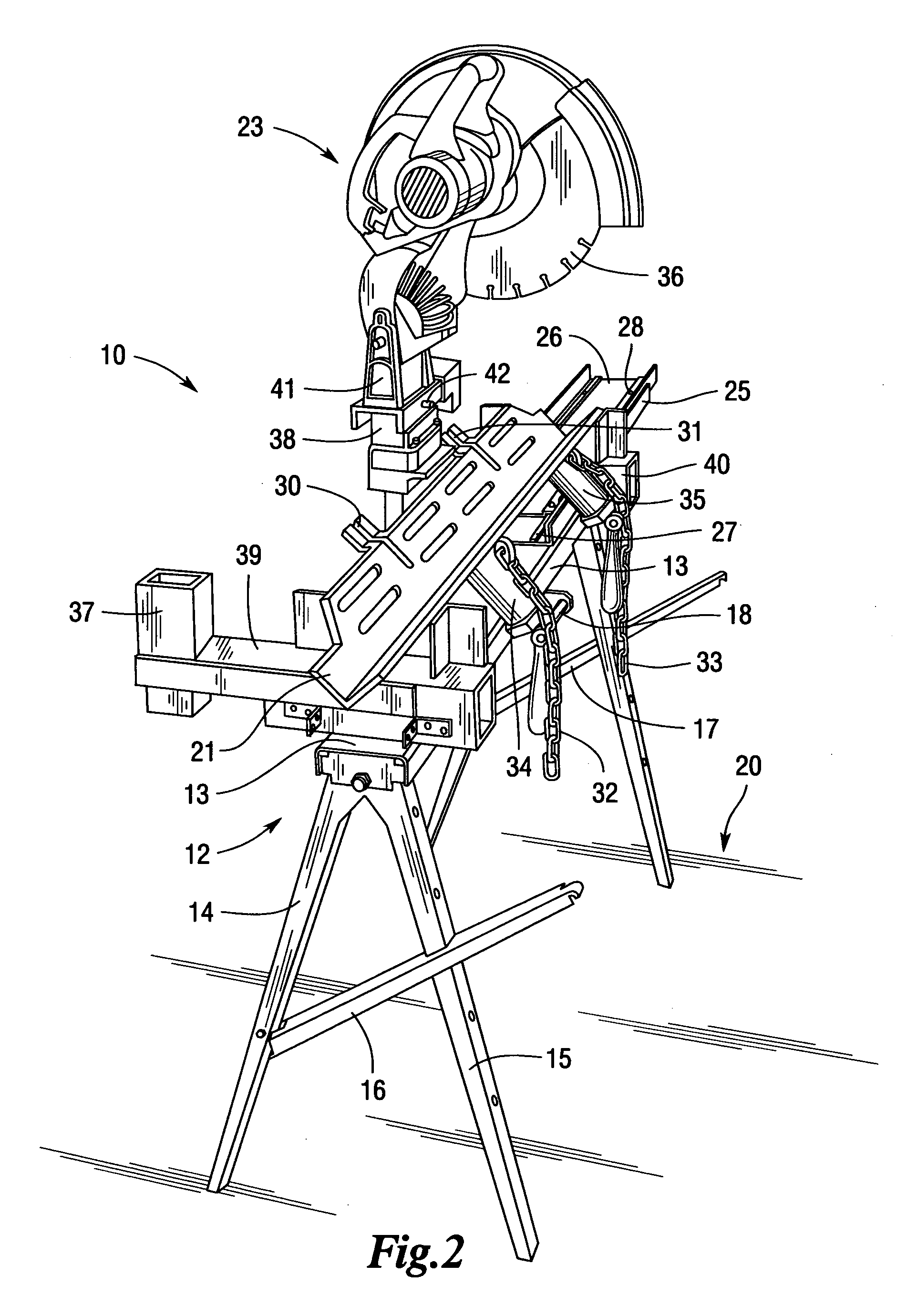
[0014]In accordance with the present invention, there is provided a portable apparatus for steadily supporting a workpiece, especially a pipe 11, while allowing cutting and related operations to be performed on the workpiece. As illustrated in FIG. 1, the portable pipe cutting apparatus 10 includes a collapsible metal work support 12 having a generally flat, horizontal member 13 and a first and second pair of legs 14, 15 attached to each end of the horizontal member 13. Each pair of legs is adjustably engaged by means of a screw or other fastener that is capable of releasably retaining the legs in the desired position. The underside of the horizontal member is hollow for receiving respectively said pairs of legs 14 and 15 for transport.

[0015]To achieve the operational position, each pair of legs 14 and 15 is respectively extended outwardly, away from the horizontal member 13, along axis “X”, to a full vertical position. Next, each pair of legs 14, 15 is extended outwardly, along hor...


PUM

PropertyMeasurementUnit
lengthsaaaaaaaaaa
lengthsaaaaaaaaaa
outer diameteraaaaaaaaaa

Abstract

A complete and portable tool for retaining round, square or other non-flat stock, especially pipes, in a secure fashion while cutting and related operations are performed thereon. The portable pipe cutting tool includes an adjustable work support, V-shaped trough, chain and tightening device, catch tray, left and right support arm bracket, mounting stand, and power tool having a base portion that, as a unit, secure the pipe in place while being cut, grooved or otherwise worked on, by an operator. The portable pipe cutting tool prevents sideways, upward, rotational or other movement of the pipe during such operations.

Description

RELATED APPLICATIONS[0001]This application claims priority to U.S. Provisional Patent Application No. 60 / 624,021 filed Nov. 1, 2004.FIELD OF THE INVENTION[0002]The invention relates to a portable apparatus for securely retaining a non-flat workpiece, especially a pipe, while cutting and related operations are performed on the workpiece.BACKGROUND OF THE INVENTION[0003]Pipe used in the construction industry is normally welded or cut prior to installation. Existing methods for cutting pipe utilize a saw and vise arrangement. At construction sites, or other locations where there is no suitable work surface, it is common for operators to locate the saw and vise directly on the ground or on sheets of wood which are supported, for example, by concrete blocks. This arrangement requires that the operator crawl or kneel down on the ground in order to cut the pipe, which in most cases, consists of dirt, concrete, shale or mud. On a typical work day, an operator performs an average of 60–100 c...

Claims


Application Information

Patent Timeline
Patent Type & Authority Patents(United States)
IPC IPC(8): B25H1/00
CPCB23D45/12Y10T83/0596Y10T83/7487Y10T83/7788
Inventor LEBERFINGER, MATTHEWMONTGOMERY, TIMOTHY
Owner LEBERFINGER MATTHEW
Learn More