Pneumatic tube system terminal and method

a technology of pneumatic tube and terminal, applied in the direction of conveyors, transportation and packaging, etc., can solve the problems of limiting the configuration options of service provider areas, limiting efficiency, and affecting the efficiency of the terminal

Active Publication Date: 2006-11-28
DIEBOLD NIXDORF
View PDF15 Cites 20 Cited by
  • Summary
  • Abstract
  • Description
  • Claims
  • Application Information

AI Technical Summary

Benefits of technology

[0011]It is a further object of an exemplary embodiment of the present invention to provide a user terminal having a movable member that allows a user to view a carrier in the user terminal through the ...

Problems solved by technology

This can present drawbacks in use of the same terminal by multiple service providers.
T...

Method used


Image

  • Pneumatic tube system terminal and method
  • Pneumatic tube system terminal and method
  • Pneumatic tube system terminal and method

Examples


Embodiment Construction

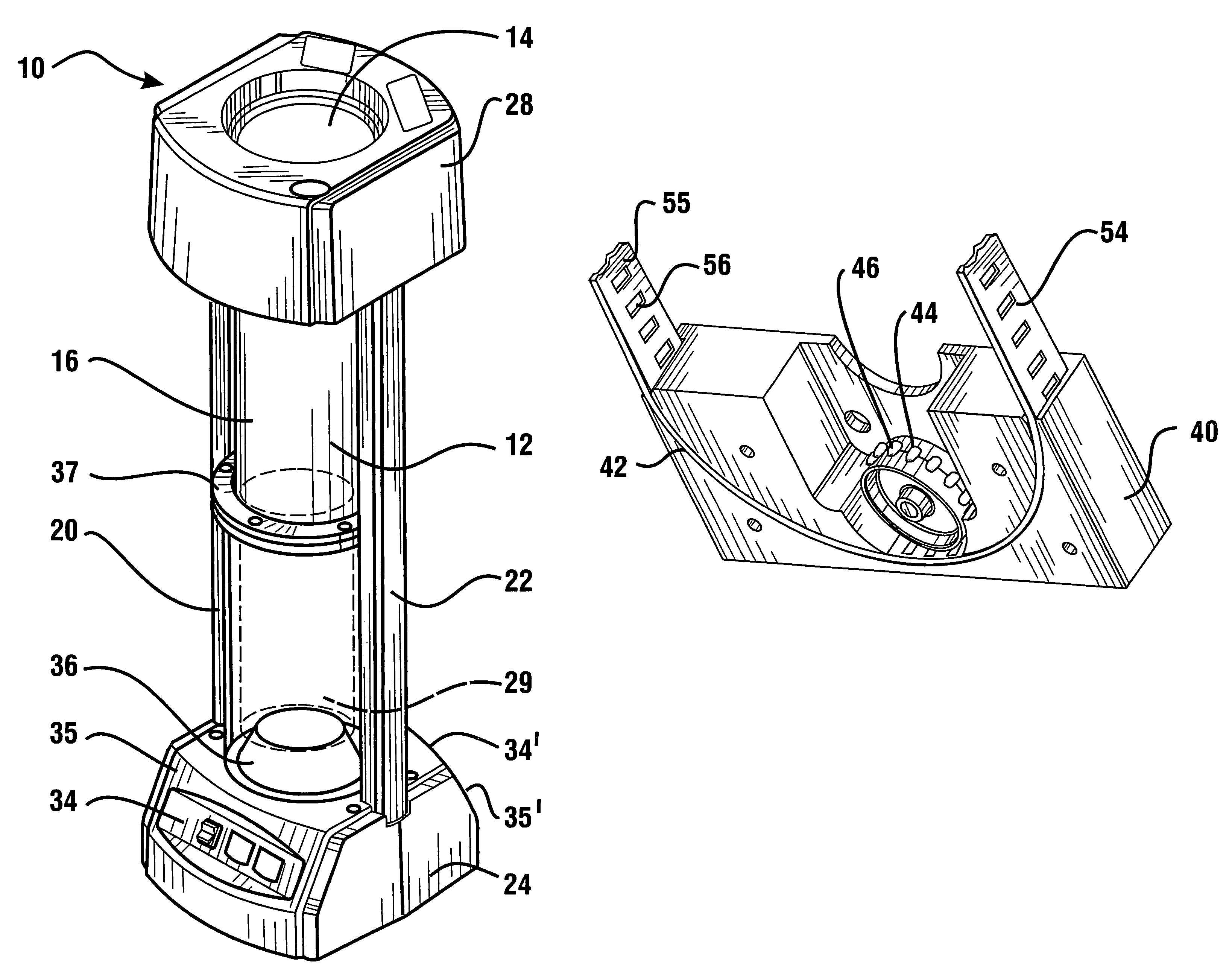
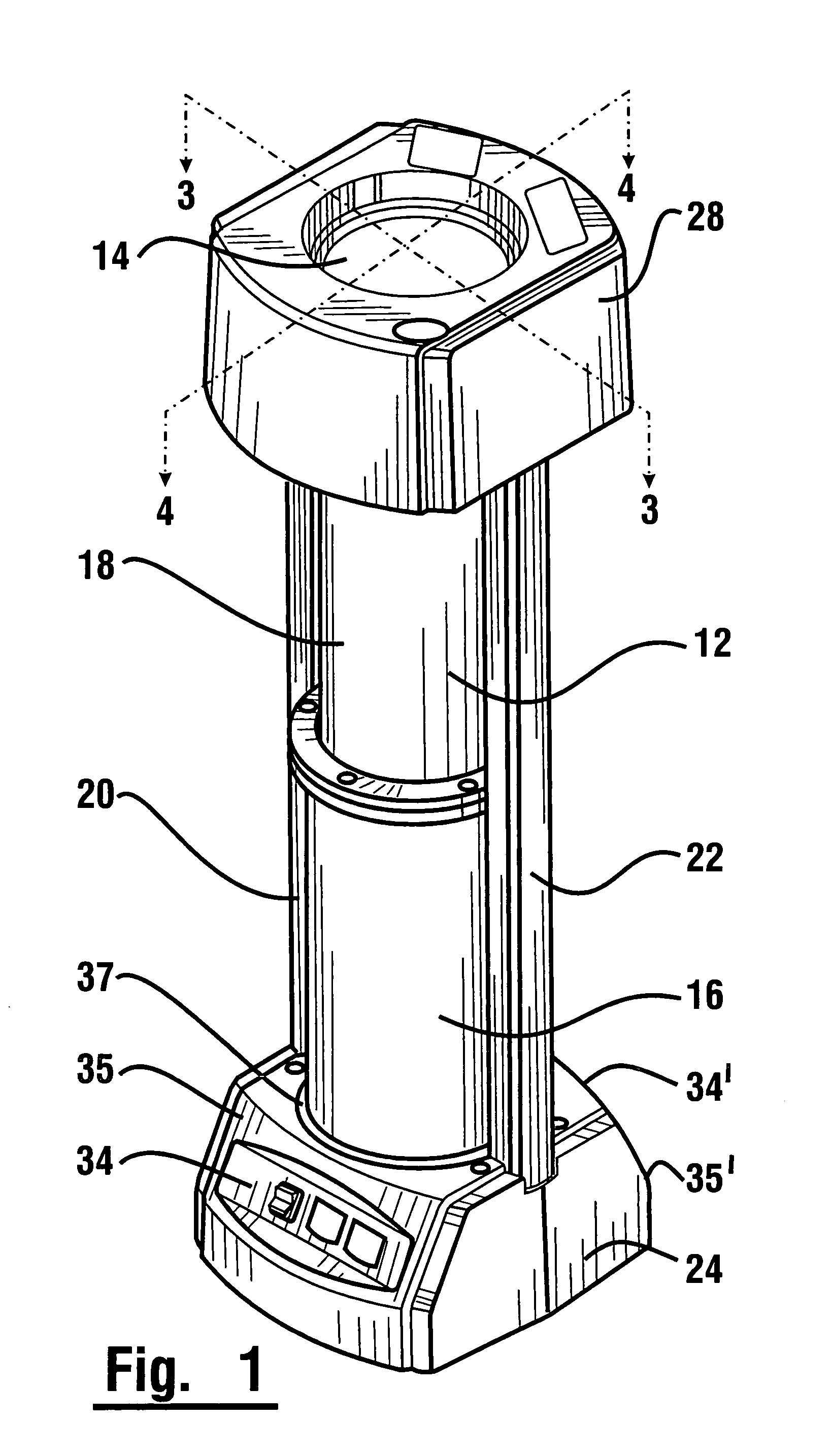
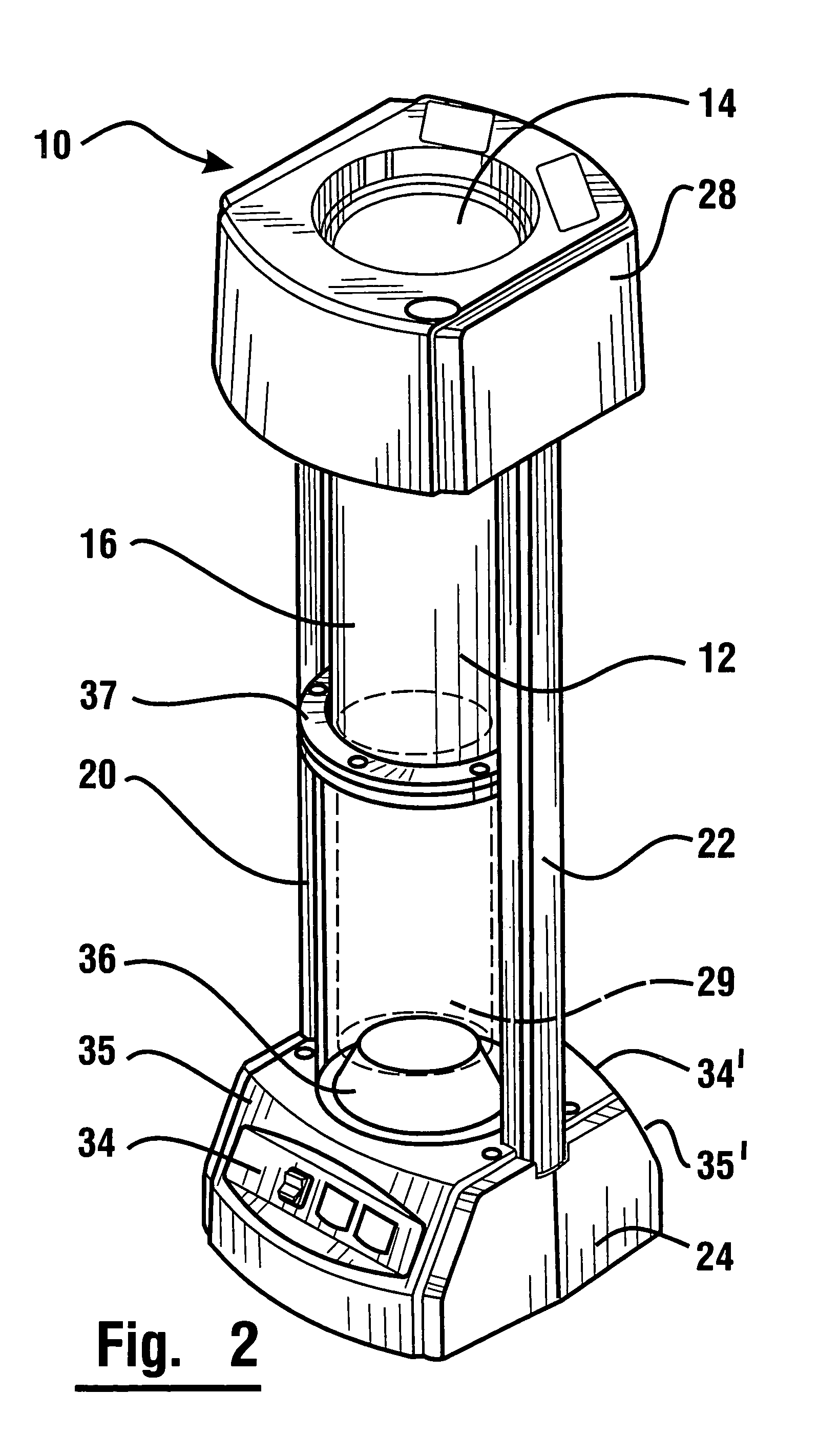
[0044]With reference to FIG. 1, there is shown an exemplary service provider user terminal 10 that is adapted to send and receive a carrier that is movable in response to air pressure through a transport tube as will be discussed in further detail below.

[0045]User terminal 10 includes a body 12 having an opening 14 therein through which a carrier may be sent and received. User terminal 10 includes a movable member 16 and a stationary upper member 18. In an exemplary embodiment both the movable member and stationary member are generally cylindrical. In other embodiments other configurations may be used.

[0046]In one exemplary embodiment, body 12 has in fixed supporting connection therewith first and second side rails 20, 22 extending vertically in disposed relation from a base 24. A cap member 28 is positioned adjacent first and second side rails 20, 22 at a position vertically disposed from base member 24.

[0047]Movable member 16 is operative to selectively move in a vertical directio...


PUM


Abstract

A pneumatic transport system including a user terminal at a service provider station having a movable member operably connected with a flexible drive member. The drive member moves within at least one side rail to vertically displace the movable member to permit access to a carrier at the user terminal. The user terminal includes control mechanisms on opposite sides of a base to enable two users to operate and access the carrier at the user terminal.

Description

CROSS REFERENCE TO RELATED APPLICATION[0001]This application claims benefit to 35 U.S.C. § 119(e) of Provisional Application 60 / 619,480 filed Oct. 15, 2004.TECHNICAL FIELD[0002]This invention generally relates to pneumatic tube transaction systems and more specifically to the construction and operation of a user terminal operated in conjunction with a transaction system.BACKGROUND ART[0003]Pneumatic tube transfer systems may be used to carry out transactions. Such systems may be used to conduct transactions between a service provider and customers at remote locations. Such systems may be used in drive-through banking applications as well as in other transaction environments.[0004]Pneumatic tube systems provide a fast and convenient way of handling customer transactions. In a typical pneumatic tube system, a customer station is positioned at a distant location from the service provider station in a bank or other institution. A teller or other service provider is positioned at a servi...

Claims


Application Information

Patent Timeline
IPC IPC(8): B65G51/26
CPCB65G51/26
Inventor CHRISTIAN, TODDGROMLEY, NEILBAKER, GARYMCINTYRE, DANIEL S.NELSON, JR., DONALD S.UJHAZY, JR., EDWARD J.
Owner DIEBOLD NIXDORF
Why Eureka
Try Eureka