Electronic control system for skid steer loader controls

a control system and loader technology, applied in the direction of electric devices, mechanical control devices, process and machine control, etc., can solve the problem that the operator can mistakenly dump out the contents of the bucket inadvertently

Inactive Publication Date: 2006-11-28
BLUE LEAF I P INC
View PDF15 Cites 38 Cited by
  • Summary
  • Abstract
  • Description
  • Claims
  • Application Information

AI Technical Summary

Benefits of technology

[0023]In accordance with a tenth preferred embodiment, the eighth preferred embodiment is further modified so that the hand / foot controls selector switch is connected to send a second enabling signal to the microprocessor, wherein the second enabling signal enables the microprocessor to generate first and second output signals in response to electronic signals received from the right foot pedal implement control sensor and the left foot pedal boom control sensor, and electronic signals received from the right hand stick implement control sensor and the left hand stick boom control sensor have no effect on the first and second output signals generated by the microprocessor.
[0024]In accordance with an eleventh preferred embodiment, the seventh preferred embodiment is further modified to include a hand / foot controls selector switch connected to send a first enabling signal to the microprocessor, wherein the first enabling signal enables the microprocessor to generate first and second output signals in response to electronic signals received from the right foot pedal implement control sensor and the left foot pedal boom control sensor, and electronic signals received from the right hand stick implement control sensor and the left hand stick boom control sensor have no effect on the first and second output signals generated by the microprocessor.

Problems solved by technology

In addition, because the boom assembly and the bucket assembly are manually controlled separately, the operator can mistakenly dump out the contents of the bucket inadvertently.

Method used


Image

  • Electronic control system for skid steer loader controls
  • Electronic control system for skid steer loader controls
  • Electronic control system for skid steer loader controls

Examples


Embodiment Construction

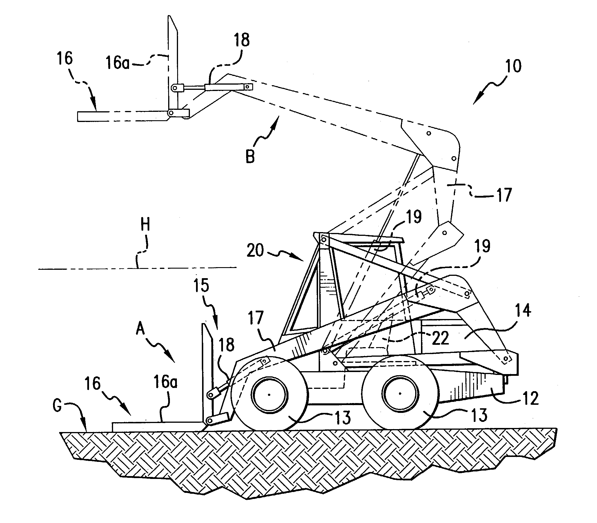
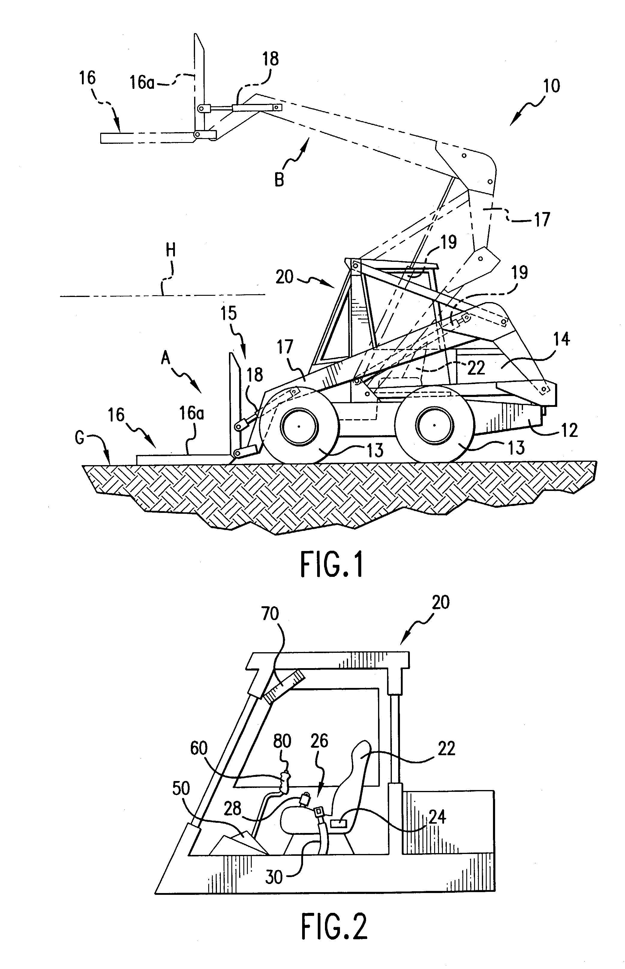
[0037]FIG. 1 shows a compact work vehicle 10, such as a skid steer loader or other like work vehicle, that includes a cab compartment 20 on the vehicle. Typically, work vehicle 10 includes a body 12 that is mounted on four wheels 13 (only two shown) suitably connected to be rotated by a transmission. The transmission is powered by an engine disposed in engine housing 14, located on the body 12. One skilled in the art would realize that the work vehicle 10 could be a tracked vehicle, a vehicle mounted on rails, or could be a machine mounted to a stationary frame without departing from the scope of the present invention.

[0038]Work vehicle 10 includes a boom arm assembly 17 that is pivotally connected to the body 12 at one end, and that is pivotally connected at its opposite end to a work implement 16, such as a loader bucket 16b, pallet forks attachment 16a, or other useful tool. As shown in FIG. 1, boom arm assembly 17 can be raised and lowered between a lower position A and an upper...


PUM


Abstract

An electronic control system for a machine having a boom assembly and an implement assembly. A microprocessor is provided having an input and generating first and second output signals. A first electrohydraulic valve is connected to receive the first output signal from the microprocessor, and connected to position the boom assembly in response to the first output signal. A second electrohydraulic valve is connected to receive the second output signal from the microprocessor, and connected to position the implement assembly in response to the second output signal. A boom position sensor is disposed on the boom assembly or the implement assembly and connected to send a boom position input signal to the microprocessor, the microprocessor being connected to receive the boom position input signal and generate at least one of the first output signal and the second output signal, thereby controlling a position of the implement assembly relative to the boom assembly.

Description

FIELD OF THE INVENTION[0001]This invention pertains to devices or machines having a hydraulic boom and bucket assembly that is operatively controlled by an electronic control system, and to the electronic control system itself. More particularly, the invention relates to a hydraulic boom and bucket assembly, such as would be mounted to a work vehicle or skid steer loader, wherein the hydraulic boom and bucket assembly is operatively controlled by a computer-controlled electronic control system carried by the work vehicle or skid steer loader.BACKGROUND OF THE INVENTION[0002]Skid steer loaders are work vehicles that include four wheels rotatably mounted to a frame, an engine mounted on the frame and connected by a transmission to rotate at least two wheels, a cab compartment mounted on the frame that includes a seat for an operator, manual controls and a display panel disposed in the cab compartment, a boom assembly rotatably mounted on the frame and connected to a pair of hydraulic ...

Claims


Application Information

Patent Timeline
Patent Type & Authority Patents(United States)
IPC IPC(8): E02F3/00E02F3/43E02F9/24
CPCE02F3/433E02F9/24Y10T74/20189Y10T74/20201
Inventor BERGER, JOHN G.HAUPT, JOHN R.
Owner BLUE LEAF I P INC
Why Eureka
Try Eureka