Three-dimensional location measurement sensor

a three-dimensional location and sensor technology, applied in the direction of optical radiation measurement, distance measurement, comonautical navigation instruments, etc., can solve the problems of affecting the accuracy of analog signals

Inactive Publication Date: 2006-11-28
SAMSUNG ELECTRONICS CO LTD
View PDF11 Cites 21 Cited by
  • Summary
  • Abstract
  • Description
  • Claims
  • Application Information

AI Technical Summary

Benefits of technology

[0018]Therefore, the present invention provides a three-dimensional location measurement sensor, which may control devices to measure the directional angles of a target object with respect to the three-dimensional location measurement sensor (e.g., the azimuth angle and inclination angle of the target object with respect to the three-dimensional location measurement sensor) independently of one another and which may easily measure the distance that the target object moved even when the object moves at high speed, and a method to measure the location of a target object and the distance between the three-dimensional location measurement sensor and the target object.

Problems solved by technology

Thus, the first group location measurement device requires a driving unit to generate a considerable amount of driving force.
An additional characteristic of the first group location measurement device is that rotating the device at a high speed while determining the location of a target object is difficult.
However, when transmitting analog signals with the use of the slip ring, the analog signals may be distorted.
The patented infrared imaging system, however, cannot set the azimuth angle and the inclination angle on the basis of an arbitrary location.
However, miniaturizing the conventional location measurement device disclosed in the '459 patent is relatively difficult because the conventional location measurement device needs to use a unique chain.
First, due to the limitations of a platform on which the conventional location measurement sensors are mounted, the conventional location measurement sensors cannot rotate within a range of 0–360 degrees. Therefore, a clear limit in determining the location of a target object that rotates more than 360 degrees exists.
Second, in some of the conventional location measurement sensors, an azimuth angle is dependent upon an inclination angle, and vice versa, in which case, precisely determining the distance from a reference location to a target object located in an arbitrary direction is substantially impossible.
Third, some conventional location measurement sensors use an omnidirectional mirror that provides a 360 degree field of view to a camera, in which case, the area of a region the camera needs to deal with increases resulting in a decrease in the resolution of an image of the region taken by the camera.

Method used


Image

  • Three-dimensional location measurement sensor
  • Three-dimensional location measurement sensor
  • Three-dimensional location measurement sensor

Examples


Embodiment Construction

[0037]Reference will now be made in detail to the embodiments of the present invention, examples of which are illustrated in the accompanying drawings, wherein like reference numerals refer to the like elements throughout. The embodiments are described below to explain the present invention by referring to the figures.

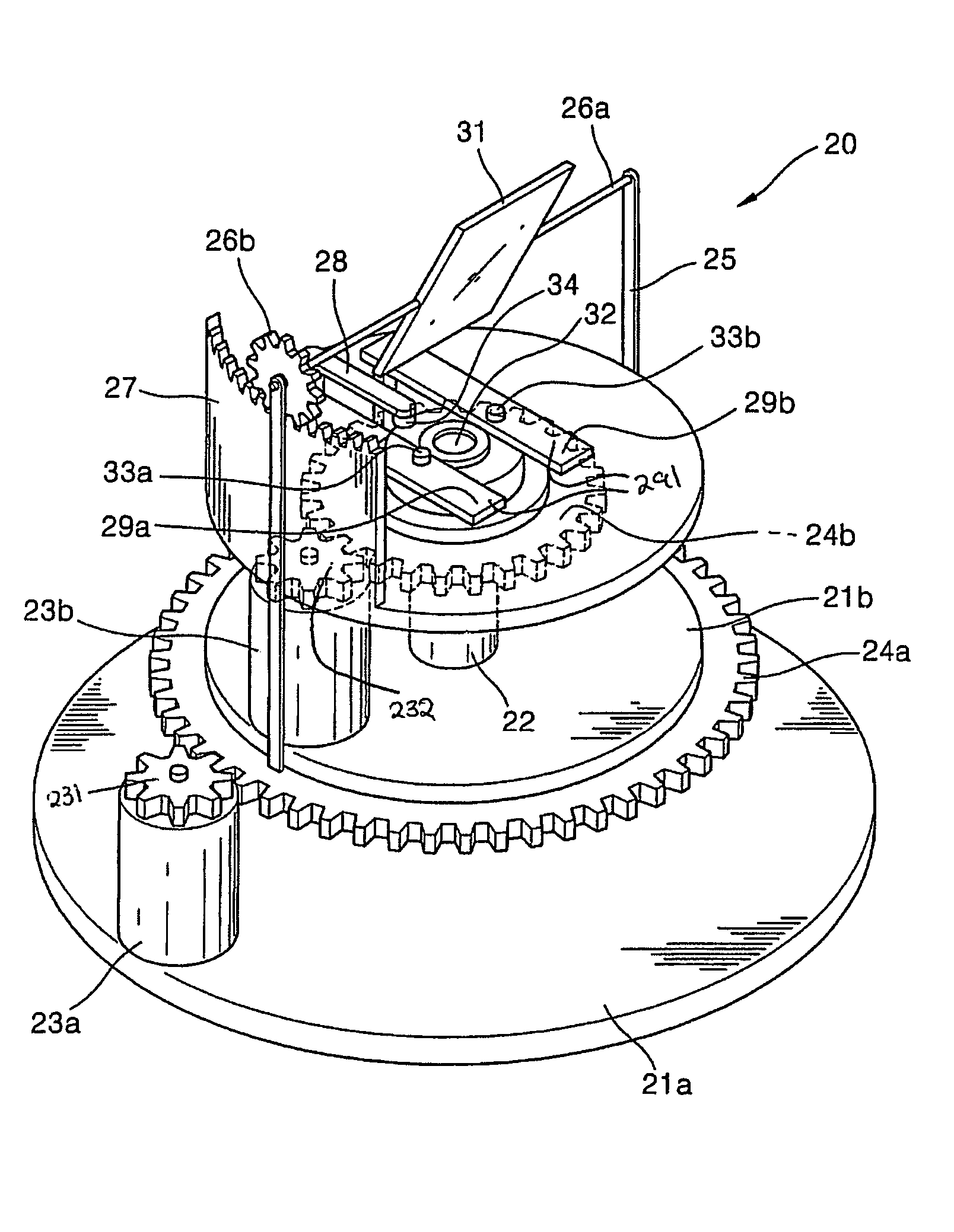
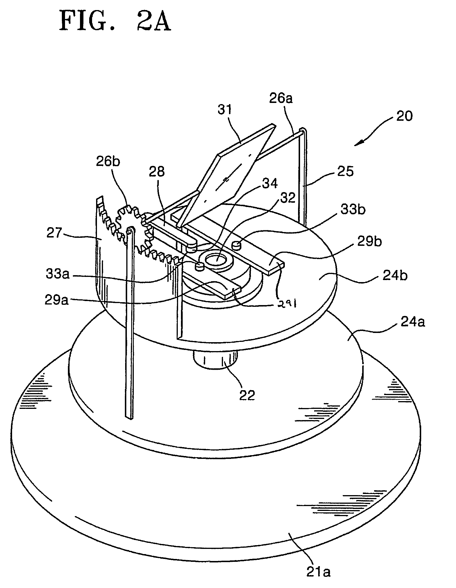
[0038]FIG. 2A is a perspective view of a three-dimensional location measurement sensor according to an exemplary embodiment of the present invention. FIG. 2B is a perspective view of a three-dimensional location measurement sensor according to another exemplary embodiment of the present invention. FIGS. 2C and 2D are a front view and a side view, respectively, of the three-dimensional location measurement sensor of FIG. 2B.

[0039]The three-dimensional location measurement sensor of FIG. 2A or 2B is divided into two blocks, i.e., a measurement block, which obtains an image reflected from the surface of a target object, and a driving unit, which drives the measurement blo...


PUM


Abstract

A three-dimensional location measurement sensor including first and second rotation plates to rotate about a fixed axial member independently of each other, a camera, formed inside the fixed axial member in the middle of the second rotation plate, a mirror, to be supported by a mirror supporting unit so as to be disposed over the camera, the mirror supporting unit being fixed to the first rotation plate, at least one light source, to be supported by a light source supporting unit so as to be disposed between the mirror and the second rotation plate, the light source supporting unit being fixed to the first rotation plate, a mark, to be supported by a mark supporting unit so as to be disposed between the mirror and the second rotation plate, the mark supporting unit being formed on the second rotation plate, and a gear unit, which is formed at an outer circumference of the second rotation plate and adjusts an inclination angle of the mirror. Accordingly, relatively easily determining the location of a target object by using the three-dimensional location measurement sensor is possible.

Description

CROSS-REFERENCE TO RELATED APPLICATION[0001]This application claims the benefit of Korean Patent Application No. 2003-80825, filed on Nov. 15, 2003, in the Korean Intellectual Property Office, the disclosure of which is incorporated herein in its entirety by reference.BACKGROUND OF THE INVENTION[0002]1. Field of the Invention[0003]The present invention relates to a three-dimensional location measurement sensor, which measures the location of a target object and the distance between the three-dimensional location measurement sensor and the target object, and a method of measuring the location of a target object and the distance between the three-dimensional location measurement sensor and the target object.[0004]2. Description of the Related Art[0005]Various location measurement methods and devices have been developed. Many conventional location measurement methods and devices use trigonometric methods to determine the location of an object by measuring the direction of the object wi...

Claims


Application Information

Patent Timeline
Patent Type & Authority Patents(United States)
IPC IPC(8): G01C21/02G01B11/14G01C3/08G01B11/00G01C3/32G01S7/481G01S17/42G02B7/182G02B26/08G02B26/10
CPCG01C3/32G01S7/481G01S17/42G02B7/1821G02B26/0833G01B11/00
Inventor JUNG, MYUNGJINBANG, SEOKWONLEE, HYOUNGKIKIM, IIHWAN
Owner SAMSUNG ELECTRONICS CO LTD
Why Eureka
Try Eureka