Image focusing in fluorescent imaging

a fluorescent imaging and image technology, applied in the field of image focusing for image capture, can solve the problems of large rate-limiting step of focusing, inability of current systems to distinguish between genuine details and noise, and sensitive to noise, and achieve the effect of rapid focus and fast throughpu

Inactive Publication Date: 2006-11-28
BIOVIEW
View PDF2 Cites 37 Cited by
  • Summary
  • Abstract
  • Description
  • Claims
  • Application Information

AI Technical Summary

Benefits of technology

[0014]The embodiments described herein overcome the difficulties explained above by removing the dependence on image details such as differential information and high frequency details, in the process of focusing. Instead, it uses the image energy, that is to say integral information and low frequency details for finding the focal position. The embodiments are thus able to be used on relatively noisy images, which can be focused rapidly. The system is particularly useful for providing fast throughput for large quantities of data.

Problems solved by technology

In high resolution scanning systems, focusing is a major rate-limiting step in that it is not unusual to find systems which spend approximately half of the imaging time on focusing.
However, current systems are unable to distinguish between genuine details and noise, and thus images with high signal to noise ratio (SNR) are required for effective focusing.
The main drawback to the above-described sequence, and a drawback which applies to a complete family of functions, is that they are sensitive to noise.
Thus, unless image quality is good, the largest contribution for the focus score comes from the noise, and both the requirements for sensitivity and for a large range are lost
Thus even slight deviations in the distance between the objective and the sample can lead to severe misfocusing of the image.
Thus in fluorescent imaging the system spends the vast majority of its time focusing, and the focusing problem is an obstacle to providing a high throughput fluorescent imaging system.

Method used


Image

  • Image focusing in fluorescent imaging
  • Image focusing in fluorescent imaging
  • Image focusing in fluorescent imaging

Examples


Embodiment Construction

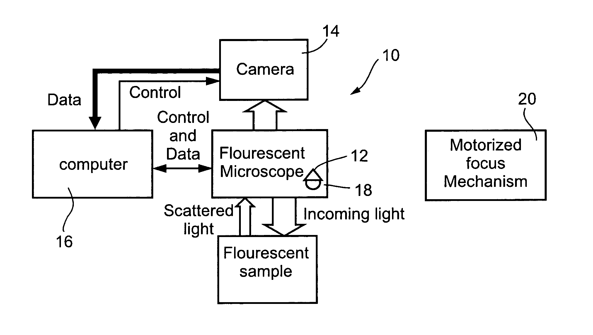
[0112]Reference is now made to FIG. 1, which is a generalized diagram showing fluorescent imaging apparatus for taking images of fluorescing samples. An apparatus 10 comprises a fluorescent microscope 12, connected to a camera 14 and to a motorized focus mechanism 20, all of which are connected to a computer 16. The computer is preferably connected to receive data from and to control both the camera and the motorized focus 20. The microscope 12 preferably comprises an illumination source 18 for illuminating a fluorescent sample. Emitted, reflected and fluorescent light is received back at the microscope 12.

[0113]As is common in microscopy, the illumination source 18 is preferably situated behind the objective lens of microscope 12, so as to illuminate the sample via the objective lens. Such a form of illumination has two effects, firstly that it concentrates illumination in the focal plane and secondly that it reduces noise in the image since the microscope picks up only emitted lig...


PUM

PropertyMeasurementUnit
focusing timeaaaaaaaaaa
exposure timeaaaaaaaaaa
distanceaaaaaaaaaa

Abstract

An imaging apparatus with an autofocus mechanism for obtaining focused images. The apparatus comprises: an objective lens, a focus controller for altering a distance between the objective lens and a sample, an object finder for finding objects of interest within the sample, for example cells, and a light intensity measurement unit which measures light intensity levels of the thus identified objects of interest. The focus control alters the sample-objective distance to maximize the light intensity levels being measured, thereby to arrive at a focus position. Objects of interest may be identified by filtering out large objects and optionally by masking out background regions. The apparatus is useful for microscopy and particularly for fluorescent imaging in which light levels are low and noise is often high.

Description

FIELD OF THE INVENTION[0001]The present invention relates to focusing for image capture and more particularly but not exclusively to fluorescent imaging and to image focusing in high resolution scanning systems.BACKGROUND OF THE INVENTION[0002]In high resolution scanning systems, focusing is a major rate-limiting step in that it is not unusual to find systems which spend approximately half of the imaging time on focusing. Thus, optimizing the focusing process is important for providing system throughput. For fluorescent imaging in particular, the situation is more extreme, as will be explained below.[0003]Conventional microscopy focus algorithms rely on the images themselves. A series of images at different focal planes is examined and the image with the largest amount of detail, or the greatest amount of information, is selected as being correctly focused. However, current systems are unable to distinguish between genuine details and noise, and thus images with high signal to noise...

Claims


Application Information

Patent Timeline
Patent Type & Authority Patents(United States)
IPC IPC(8): H01J27/00G02B7/28G01N21/64G02B7/36G02B21/16G02B21/24G02B21/36H04N5/232
CPCG01N21/6458G02B21/16G02B21/244G02B21/245G02B21/367
Inventor KAPLAN, ERANFREIBERGER, AVNER
Owner BIOVIEW
Why Eureka
Try Eureka