
Apparatus for focusing particle beam using radiation pressure

a particle beam and radiation pressure technology, applied in the field of apparatus for focusing particle beams, can solve the problems of limited size of available particles, the width of particle beams that can be obtained with respect to the set size of particles, and the width of particle beams that can be obtained under the set flow condition, so as to achieve the effect of increasing the number of particles

Inactive Publication Date: 2006-11-28
KOREA ADVANCED INST OF SCI & TECH
View PDF5 Cites 4 Cited by
  • Summary
  • Abstract
  • Description
  • Claims
  • Application Information

AI Technical Summary

Benefits of technology

[0010]It is another object of the present invention to provide an apparatus for focusing particle beams using a radiation pressure capable of obtaining a narrower particle beam width as compared to the same flow amount condition and a particle size. As a result, it is possible to obtain the increased number concentration of particles.

Problems solved by technology

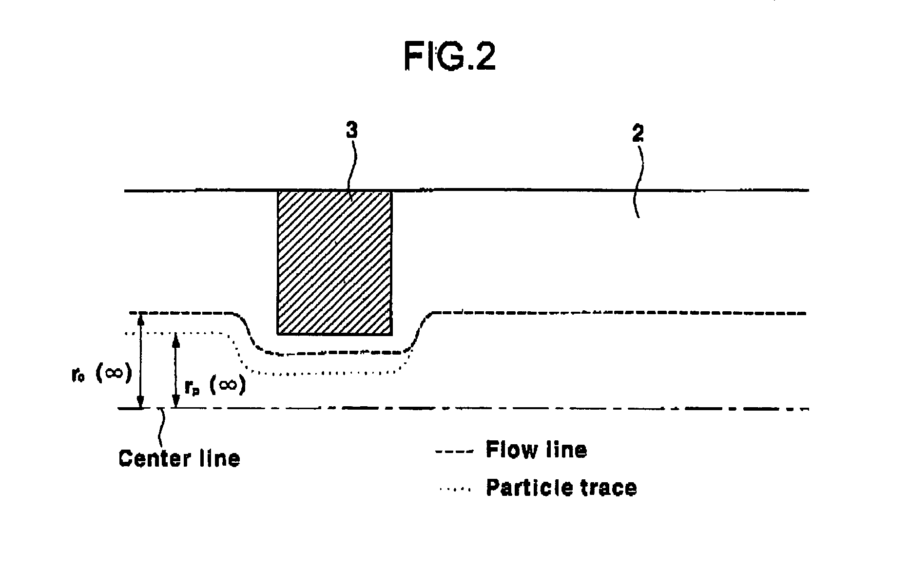
However, in the case that the particle beam apparatus using the aerodynamic lens is adapted, the width of the particle beam that can be obtained under the set flow condition and the size of available particles are limited.
In addition, on the contrary, there are disadvantages that the width of the particle beam that can be obtained with respect to the set size of the particle and the available flow amount are limited.
In the case that the multistage type aerodynamic lens is used, the particle beam apparatus gets complicated, and the disadvantages in the operation particle size and the flow condition of the aerodynamic lens still remain.

Method used


Image

  • Apparatus for focusing particle beam using radiation pressure
  • Apparatus for focusing particle beam using radiation pressure
  • Apparatus for focusing particle beam using radiation pressure

Examples


embodiments

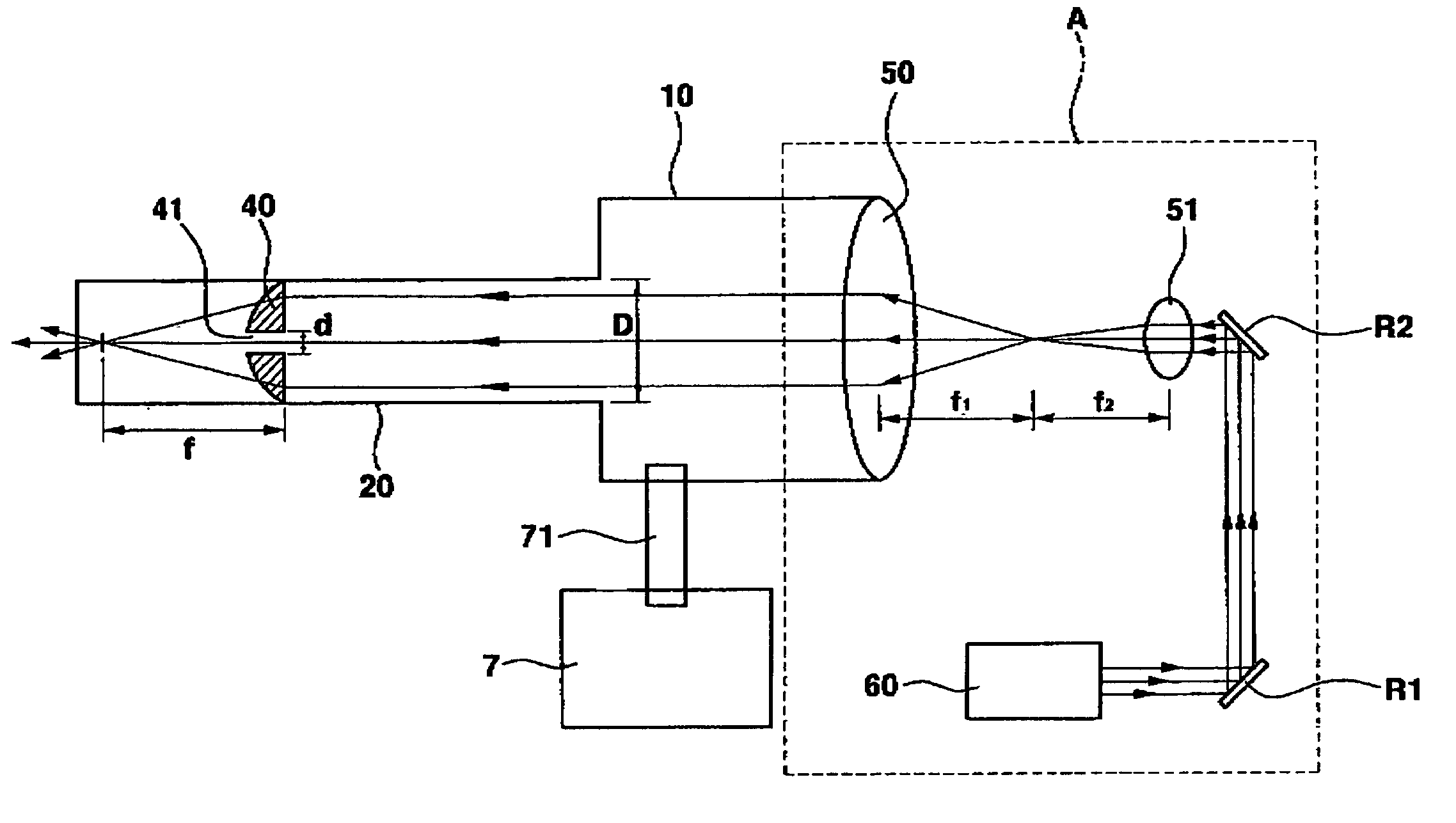
[0036]In order to explain the particle beam focusing apparatus using a radiation pressure according to the present invention, there are provided a flow tube having a diameter (D) of 25 mm, and an orifice part 40 having a hole diameter (d) of 2.5 mm and a focusing distance (f) of 35 mm of the lens. The particles adapted are PSL, and the diameters of the particles are 0.5 μm, 1.0 μm, and 2.5 μm. The laser adapted in the laser beam apparatus 60 is a Ar—Ion CW laser. The output of the Ar—Ion CW laser having the minimum value of the particle beam width when the radiation pressure is applied using the laser with respect to the size of the particle adapted is about 0.2 W. In the orifice part 40, the Reynolds number (Re) maintains about 300˜700 so that the particle beams can be formed at the atmospheric pressure based on the air-particle flow amount. Here, the Reynolds number may be expressed like the following.

Re(Reynolds number)=ρVd / μ

[0037]Here, ρ represents the density of the air, and V ...


PUM


Abstract

The present invention relates to an apparatus for focusing particle beams using a radiation pressure capable of obtaining the same flow amount and a narrower particle beam width with respect to the particle size and a higher numeral density. It is possible to form the particle beams by applying the radiation pressure to the particles with respect to the flow condition that cannot form the particle beams with respect to the set particle sizes. There is provided an apparatus for focusing particle beams using a radiation pressure, comprising an orifice part that is provided at a predetermined portion of the flow tube, and a lens having a hole with a predetermined diameter for thereby focusing the particle flow into a particle beam and applying a radiation pressure to the flow particles; and a light source supply part (A) provided at a portion opposite to the discharge outlet of the mixing tube.

Description

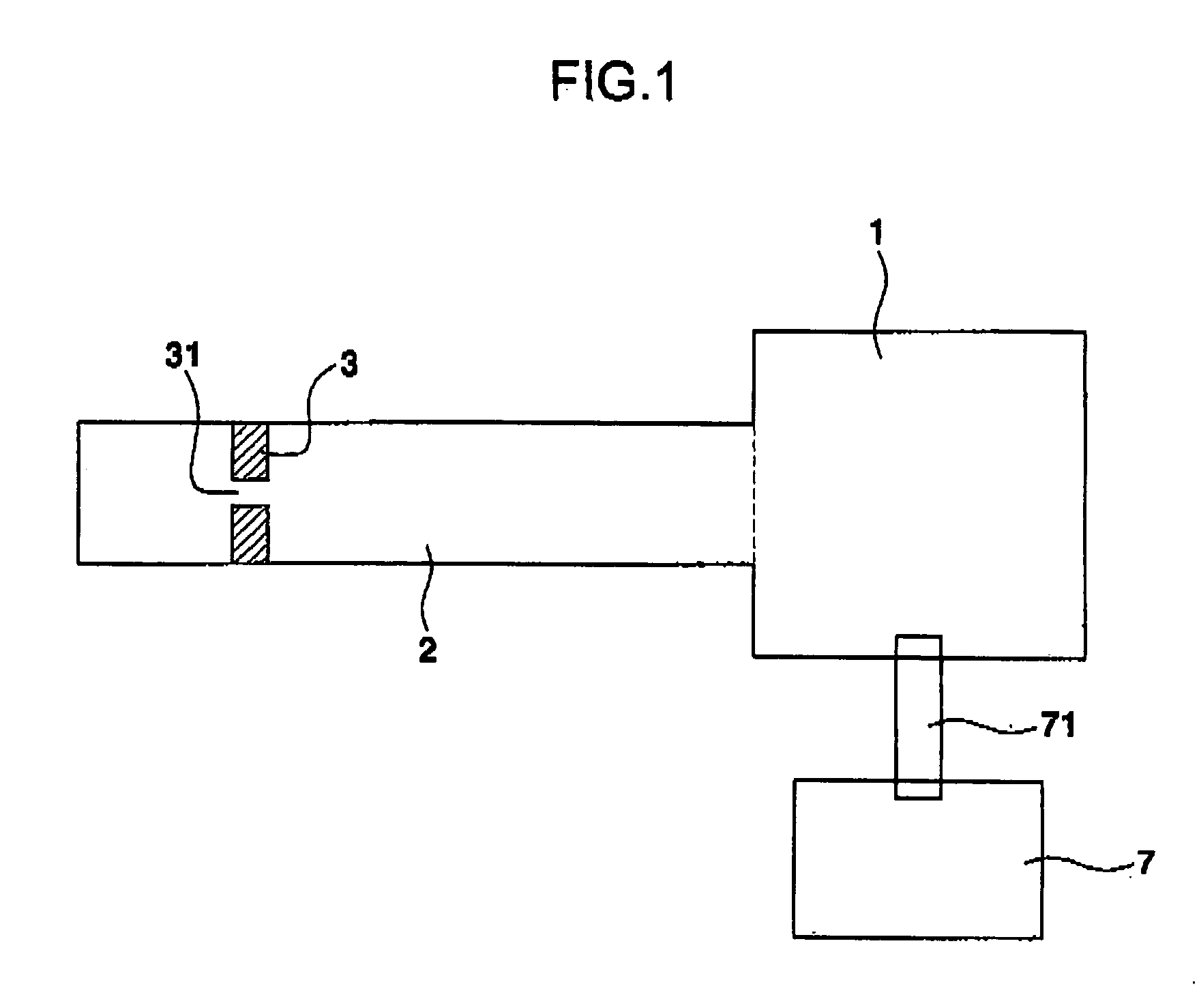
BACKGROUND OF THE INVENTION[0001]1. Field of the Invention[0002]The present invention relates to, an apparatus for focusing a particle beam, and in particular to an apparatus for focusing a particle beam using a radiation pressure capable of controlling the width of a particle beam[0003]2. Description of the Background Art[0004]A particle beam represents that the flow of a particle has a beam type. In the case that particles flow in a beam type narrow region, the number concentration of particles is increased, so that it is possible to monitor particles with high accuracy. In addition, since the particles continuously flow in a beam type, it is possible to measure the sizes of particles and a particle size distribution in real time. Therefore, a particle beam focusing apparatus has been used for a mass analyzer or a chemical composition analyzer. Recently, it has been used in a micro particle monitoring apparatus in which particles rarely exist like in a semiconductor process.[0005]...

Claims


Application Information

Patent Timeline
Patent Type & Authority Patents(United States)
IPC IPC(8): H01J41/04
CPCG01V8/00H01J49/0445G01N15/1404G01N1/40H01J27/024H01J37/30
Inventor KIM, SANG SOOPARK, HYUNG HOKIM, SANG BOK
Owner KOREA ADVANCED INST OF SCI & TECH
Learn More