
Actuator device

a technology of actuators and actuators, applied in the field of actuators, can solve the problems of the area of a region displaced by an actuator, and the inability to increase the effective area, so as to achieve the effect of increasing the effective area and increasing the yield

Inactive Publication Date: 2006-11-28
NGK INSULATORS LTD
View PDF57 Cites 8 Cited by
  • Summary
  • Abstract
  • Description
  • Claims
  • Application Information

AI Technical Summary

Benefits of technology

The present invention provides an actuator device that can compensate for defective actuators with normal actuators, increasing the yield and effective area of the actuator device. The actuator device has multiple actuators arranged in a plane, and a plate member to which drive forces from the actuators are transmitted. Even if one actuator fails, the entire plate member is not affected, making it possible to compensate for the failure. The actuators have vibrating sections, and the plate member has concavities and convexities to increase flexural rigidity. The actuators and plate member can be connected by displacement transmitters. The actuator device can be used as a display device, increasing the aperture ratio of a pixel and allowing for increased luminance and contrast. The actuator device has a high yield and increased effective area. The invention provides an improved actuator device for use in display devices.

Problems solved by technology

If one actuator 206 is defective in such a configuration, then a spot corresponding to that actuator 206 is displayed as a black or white dot regardless of an image displayed by the display device 200, tending to cause a disadvantage to increase the image quality.
Specifically, even if one actuator is defective in the conventional actuator device, then since the defective actuator adversely affects the quality of the actuator device, it tends to pose a limitation to increase the yield.
Another problem is that the area of a region that is displaced by an actuator, i.e., an effective area, cannot be increased.

Method used


Image

  • Actuator device
  • Actuator device
  • Actuator device

Examples


first embodiment

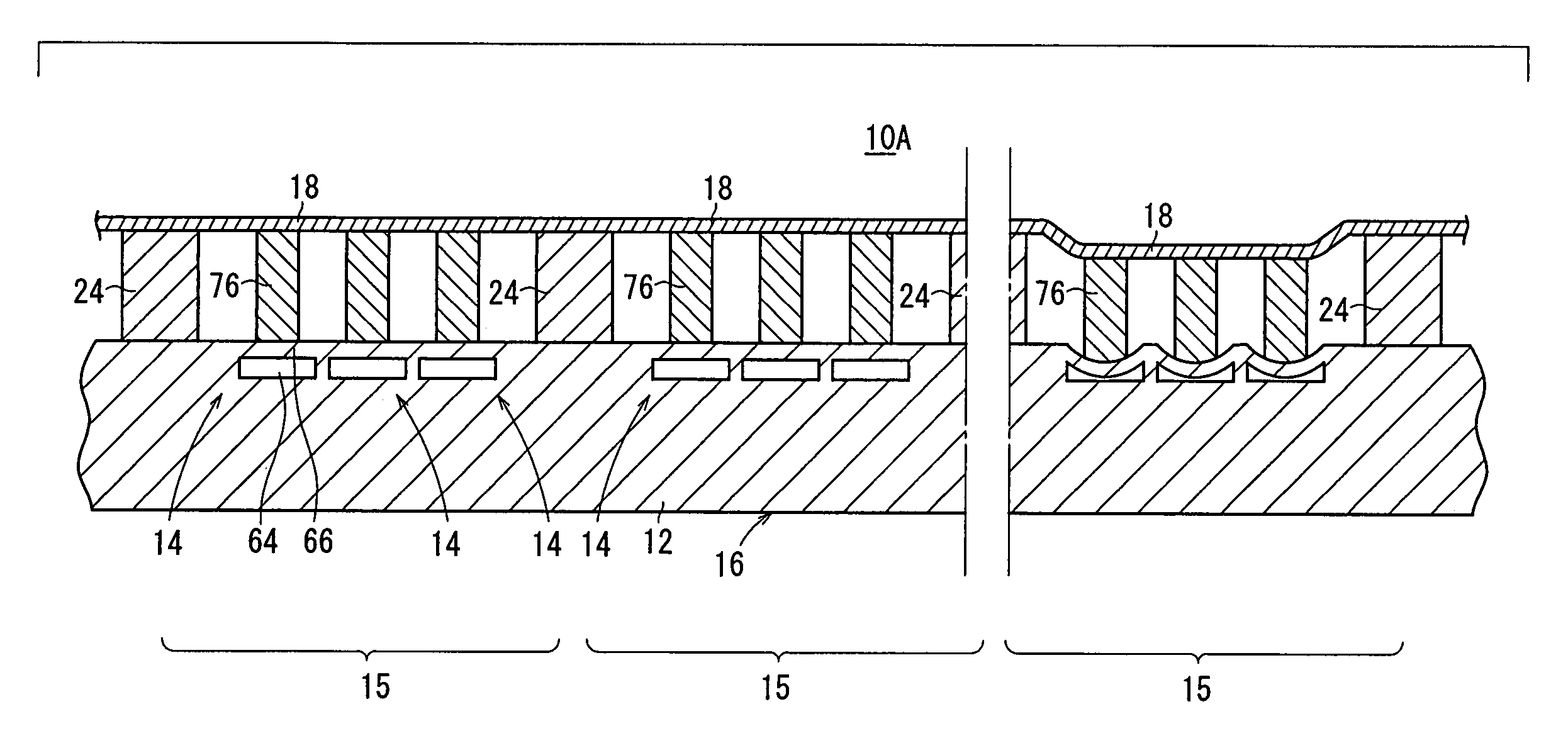
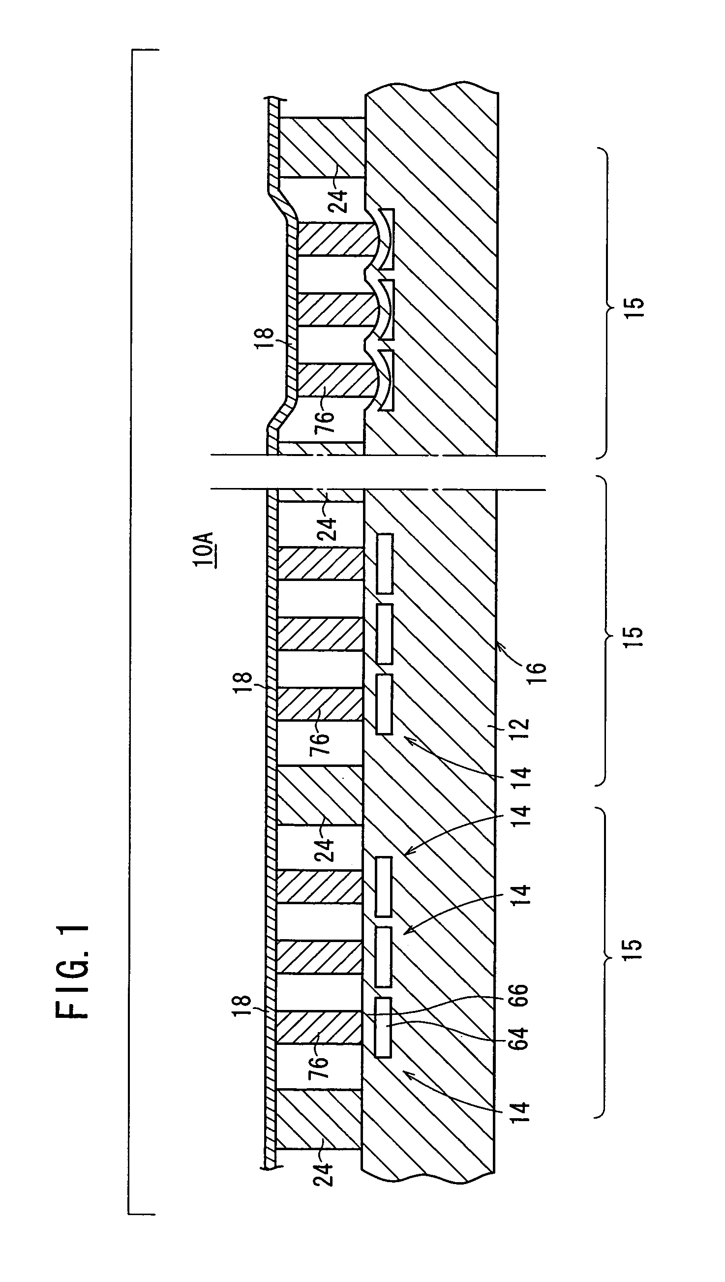
[0129]As shown in FIG. 1, an actuator device 10A has a drive section 16 including a plurality of actuators 14 arranged in a plane on a substrate 12, and a first plate member 18 to which drive forces from the actuators 14 of the drive section 16 are transmitted.

[0130]A plurality of spacers 24 are disposed between the first plate member 18 and the substrate 12, forming m cells 15. N actuators 14 are assigned to each of the cells 15. Each of the cells 15 may have the same size (the cells serve as unit cells) or may have different sizes.

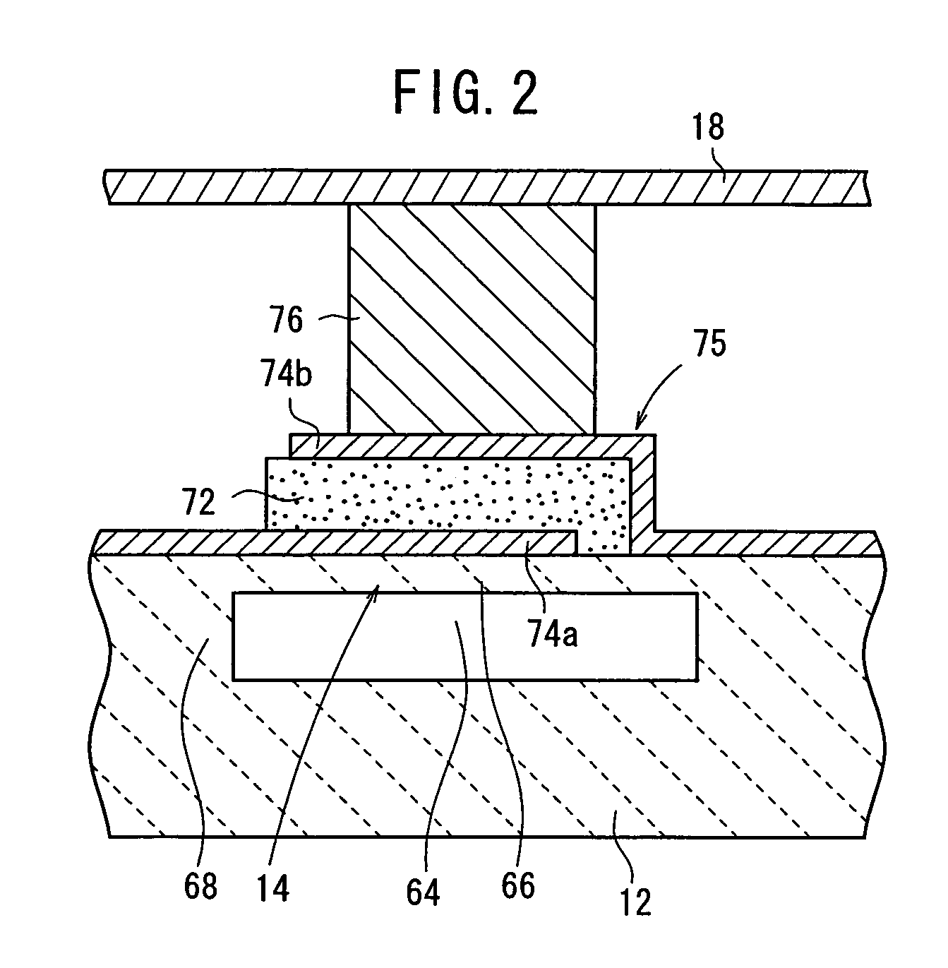
[0131]Each of the actuators 14 comprises a cavity 64, a vibrating section 66, and a fixed section 68 formed in the substrate 12. Of the substrate 32, a portion where the cavity 64 is defined is thin, and the other portion is thick. The thin portion is of a structure easily vibratable under external stresses and functions as the vibrating section 66. The portion other than the cavity 64 is thick and functions as the fixed section 68 supporting the vibrat...

fourth embodiment

[0294]Examples in which the actuator device 10D is applied to other uses than the display device will be described below with reference to FIGS. 45 through 38C.

[0295]A variable capacitor 120 according to a specific example shown in FIG. 45 has a drive section 36 including a plurality of actuators 34 arranged in a plane on an actuator substrate 32, a fixed electrode 122 comprising a single metal plate disposed facing the drive section 36, and a movable electrode 124 comprising a single metal plate which is disposed between the actuator substrate 32 and the fixed electrode 122 and to which drive forces from the actuators 34 of the drive section 36 are transmitted through displacement transmitters 76. The fixed electrodes 122 are fixed to the actuator substrate 32 by spacers 112 that are interposed between the fixed electrode 122 and the actuator substrate 32.

[0296]With the variable capacitor 120, the movable electrode 124 is moved toward and away from the fixed electrode 122 when the...

fifth embodiment

[0304]An actuator device 10E which is free of the substrate 12 will be described below with reference to FIG. 49.

[0305]As shown in FIG. 49, the actuator device 10E according to the fifth embodiment employs a laminated assembly 156 of a vibrating plate layer 152 and a piezoelectric function layer 154, instead of the substrate 12.

[0306]The piezoelectric function layer 154 has a plurality of lower electrodes 74a formed on the vibrating plate layer 152, a piezoelectric / electrostrictive layer 72 formed on the entire surface of the vibrating plate layer 152 including the lower electrodes 74a, and a plurality of upper electrodes 74b formed on the piezoelectric / electrostrictive layer 72. The vibrating plate layer 152 amplifies the displacement amount of the piezoelectric / electrostrictive layer 72. The laminated assembly 156 has a structure including an array of actuators 14, and serves as a drive section 16. The vibrating plate layer 152 may be made of the same material as or may be made o...


PUM


Abstract

An actuator device has a drive section including a plurality of actuators arranged in a plane on a substrate, and a single first plate member to which drive forces from the actuators of the drive section are transmitted. A plurality of spacers are disposed between the first plate member and the substrate, forming m cells. Each of the actuators has a cavity, a vibrating section and a fixed section formed on the substrate. The rigidity of the first plate member is greater than the rigidity of the vibrating section of the actuator.

Description

[0001]This application claims the benefit of Japanese Application No. 2003-277887, filed Jul. 22, 2003, and Japanese Application No. 2004-195070, filed Jun. 30, 2004, the entireties of which are incorporated herein by reference.BACKGROUND OF THE INVENTION[0002]1. Field of the Invention[0003]The present invention relates to an actuator device which is applicable to a display device and which is also applicable to various applications including an optical modulator, a variable capacitor, etc.[0004]2. Description of the Related Art[0005]It is known in the art that an actuator device having a plurality of actuators can be applied to a display device, and can also be applied to various applications including an optical modulator, a variable capacitor, etc. (see Japanese Laid-Open Patent Publication No. 11-339561, for example). With regard to the display device, for example, the applicant of the present application has proposed a novel display device in order to achieve the following adva...

Claims


Application Information

Patent Timeline
Patent Type & Authority Patents(United States)
IPC IPC(8): H01L41/08B81B3/00H10N30/00G02B26/08H10N30/20H10N30/80
CPCB81B3/0018G02B26/0841G02B26/0858H01L41/083H01L41/0973H04R17/005H01L41/0474B81B2201/032H04R2201/003H10N30/874H10N30/2047
Inventor TAKEUCHI, YUKIHISANANATAKI, TSUTOMUKIMURA, KOJISHIMOGAWA, NATSUMIAKAO, TAKAYOSHI
Owner NGK INSULATORS LTD
Learn More