Method of programming security control panels for door entry device compatibility

a technology for door entry devices and control panels, applied in the field of security systems, can solve the problems of system not properly armed and disarmed, system not properly arming and disarming, so as to eliminate false alarms of entry delay and reliable disarming the system

Active Publication Date: 2006-11-28
ADEMCO INC
View PDF8 Cites 22 Cited by
  • Summary
  • Abstract
  • Description
  • Claims
  • Application Information

AI Technical Summary

Benefits of technology

[0010]This arrangement solves the assisted security system interface problem in several ways. It provides a means to arm and disarm the security system with a minimum of intervention from the end user. It provides a means to ensure that the system is armed when needed, eliminating the unoccupied and unarmed premises problem. It provides a means to reliably disarm the system to eliminate entry delay false alarms. It also provides a means to detect forced entry and sound the alarm instead of disarming like those in the prior art.

Problems solved by technology

Problems arise when the system is not properly armed and disarmed.
Typical problems include not disarming the system before the alarm sounds, arming away when occupants plan to stay within the protected space, and not arming the system when the premises are unoccupied.
A major drawback with this arrangement occurs when the door is forced open (i.e. a “kick-in” by an intruder) and the bolt disengages from the jamb switch without the use of a key.
Although this is an unauthorized entry, the alarm system will disarm allowing the perpetrator full access to the premises.
Another major drawback with this arrangement is that the deadbolt switch needs to be wired to the control panel.
As such, this is a labor-intensive installation that needs improvement.

Method used


Image

  • Method of programming security control panels for door entry device compatibility
  • Method of programming security control panels for door entry device compatibility
  • Method of programming security control panels for door entry device compatibility

Examples


Embodiment Construction

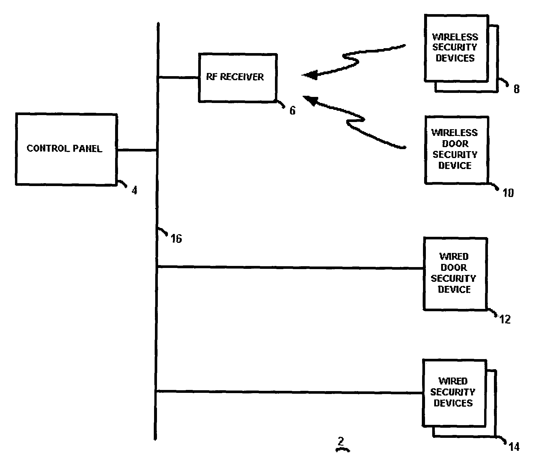
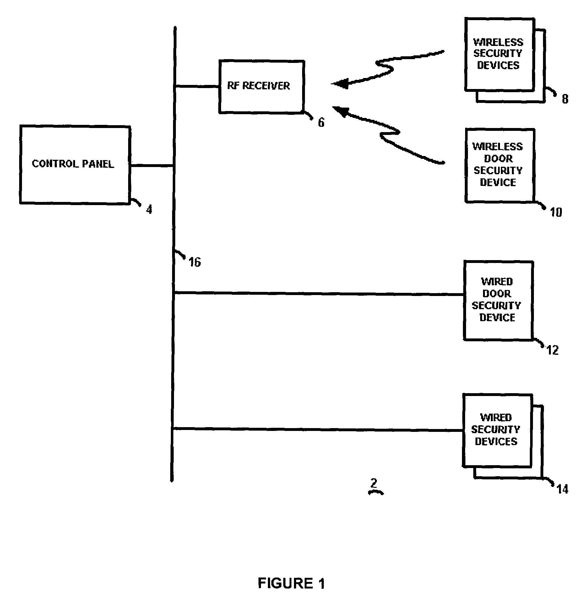
[0020]The preferred embodiment of the present invention will now be described with respect to the Figures. As also described in co-pending application Ser. No. 10 / 462,449 and repeated herein for clarity, FIG. 1 illustrates a block diagram of a security system 2 having a control panel 4 connected by a security system bus 16 to one or more wired security devices 14 as well known in the art. Security devices 14 may include, for example, a passive infrared (PIR) sensor for sensing motion of a protected volume of space, a smoke or heat detector, a glass break sensor, and the like. In addition, an RF receiver 6 is connected to the control panel 4, and provides wireless communications with wireless security devices 8 as well known in the art. These wireless security devices may also be PIR sensors, glass break sensors, etc. The control panel 4 operates as known in the art (except as modified in accordance with the present invention to interoperate with the door security devices described h...


PUM


Abstract

A method of operating a control panel in a security system that includes a door entry security device in a housing suitable for mounting within a recess of a doorjamb or door of a premises. The control panel is programmed to register a system arm / disarm device and a door closure device, both with the same identification number, such that the control panel recognizes that identification number to be associated with a door entry security device. In the even that the control panel receives, while in an armed state, an alarm signal from a security device in the security system and then receives a system disarm message, then the control panel determines if the system disarm message was received from a system arm / disarm device that has been registered as a door entry security device. If the control panel determines that the system disarm message was received from a system arm / disarm device that has been registered as a door entry security device, then the system disarm message is ignored; and if the control panel determines that the system disarm message was not received from a system arm / disarm device that has been registered as a door entry security device, then the system disarm message is followed.

Description

CROSS-REFERENCE TO RELATED APPLICATIONS[0001]This application is a continuation-in-part application of application Ser. No. 10 / 462,449 filed Jun. 16, 2003 now U.S. Pat. No. 6,963,280 and owned by the assignee of this application, the specification of which is incorporated by reference herein.TECHNICAL FIELD[0002]This invention relates to security systems, and in particular to a security device that operates in conjunction with an entry door to selectively arm and / or disarm the security system in an automatic manner and a method of operation of the security system and control panel utilizing this security device.BACKGROUND ART[0003]Alarm systems monitor sensors to determine the presence of people within a protected space. If the alarm system detects a breach of the protected space it will respond based on the state of the system. Possible system states include “disarmed”, “armed stay”, and “armed away.” If the system is disarmed it will not cause an alarm due to a breach of perimeter...

Claims


Application Information

Patent Timeline
Patent Type & Authority Patents(United States)
IPC IPC(8): E05B45/06E06BG08B13/08G08B13/22
CPCE05B45/06G08B13/06G08B13/08G08B25/008G08B25/14E05B2045/0695
Inventor ESKILDSEN, KENNETH GCHEN, HONG JYH
Owner ADEMCO INC
Why Eureka
Try Eureka