Laser projection system
a laser projection and laser technology, applied in the field of high-resolution video projection systems, can solve the problems of not providing a laser projection system that combines sufficient resolution, brightness and color, rivals or exceeds the resolution of film, etc., and achieves the effect of reducing the size and cost of these components and great flexibility
- Summary
- Abstract
- Description
- Claims
- Application Information
AI Technical Summary
Benefits of technology
Problems solved by technology
Method used
Image
Examples
example 1
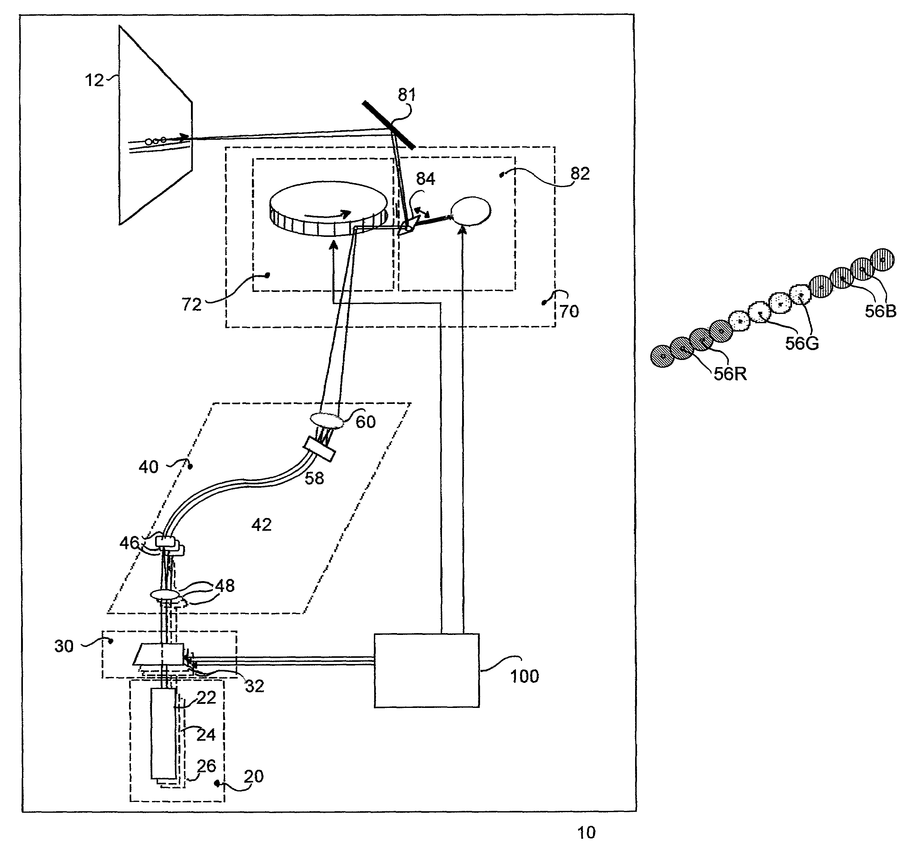
[0252]Example 1 illustrates reordering of the video signal to scan complete frames with an emitting end array shown in FIG. 27 and a corresponding spot pattern shown in FIG. 27S of 4 rows by 3 spots per row in a “log” configuration, with the assumptions shown in Tables EX-1A through EX-1C. FIGS. 28A–28H and Table EX-1A describe the lines written at each scan pass s1, s2, s3, . . . . We further assume a uniform or equal physical distance between rows of emitting ends in the output head 58, which is not necessarily required, as described later in connection with other examples. Further, for FIGS. 28A–28H lines written by RowD, RowC, RowB, RowA of emitting ends are indicated by DDDD, CCCC, BBBB, AAAA, respectively.
[0253]For this Example 1, as shown by FIGS. 28A through 28D and described in Table EX-1A, the effective row spacing of 3 lines writes the first four lines of the frame during scan passes s1, s2 and s3 in a 4,1,2,3 order. FIGS. 28E through 28H show and Table EX-1A describes th...
example 2
[0255]Example 2, described in Table EX-2 below and schematically shown in FIGS. 5S, 29A through 29D is an example of how an effective row spacing that is an even multiple of the number of rows of emitting ends or spots (in this Example 2, an effective row spacing of 4) with a vertical line adjustment between scan passes equal to the number of rows of emitting ends or spots (in this Example 2, a vertical adjustment of 4 lines) is not effective in the exemplary system.
[0256]
TABLE EX-1BOutput Head Configuration (spot pattern)- Rows: 4 Spots / Row: 3Corresponding Figures: FIGS. 28, 30 Vertical Adjustment: 4 linesPattern of Spots: Log Effective Row Spacing(all rows): 3 linesScan Pass: 3 Blank = b Spot Spacing within Row: 4 dotsRowARowBRowCRowDBlueGrnRedBlueGrnRedBlueGrnRedBlueGrnRedLinetime t1Dot Locations3bbb...6bb1...9bbb...12 bb1Linetime t2Dot Locations3bbb...6bb2...9bbb...12 bb2Linetime t3Dot Locations3bb1...6bb3...9bb1...12 bb3Linetime t5Dot Locations3bb3...6b15...9bb3...12 b15Li...
example 3
[0260]Similarly, in Example 3, described in Table EX-3 and schematically shown in a typical frame format in FIGS. 30A through 30D it may be seen that changing the line adjustment for the four line effective row spacing output head to a five line adjustment still fails to write lines 3, 8, . . . , etc.
PUM
 Abstract
Description
Claims
Application Information
 - R&D
- Intellectual Property
- Life Sciences
- Materials
- Tech Scout
- Unparalleled Data Quality
- Higher Quality Content
- 60% Fewer Hallucinations
Browse by: Latest US Patents, China's latest patents, Technical Efficacy Thesaurus, Application Domain, Technology Topic, Popular Technical Reports.
© 2025 PatSnap. All rights reserved.Legal|Privacy policy|Modern Slavery Act Transparency Statement|Sitemap|About US| Contact US: help@patsnap.com


