
Tape drive

a magnetic tape and drive technology, applied in the direction of instruments, mechanical tension control of carriers, recording signal processing, etc., to achieve the effect of high density recording

Active Publication Date: 2006-11-28
FUJIFILM CORP +1
View PDF6 Cites 7 Cited by
  • Summary
  • Abstract
  • Description
  • Claims
  • Application Information

AI Technical Summary

Benefits of technology

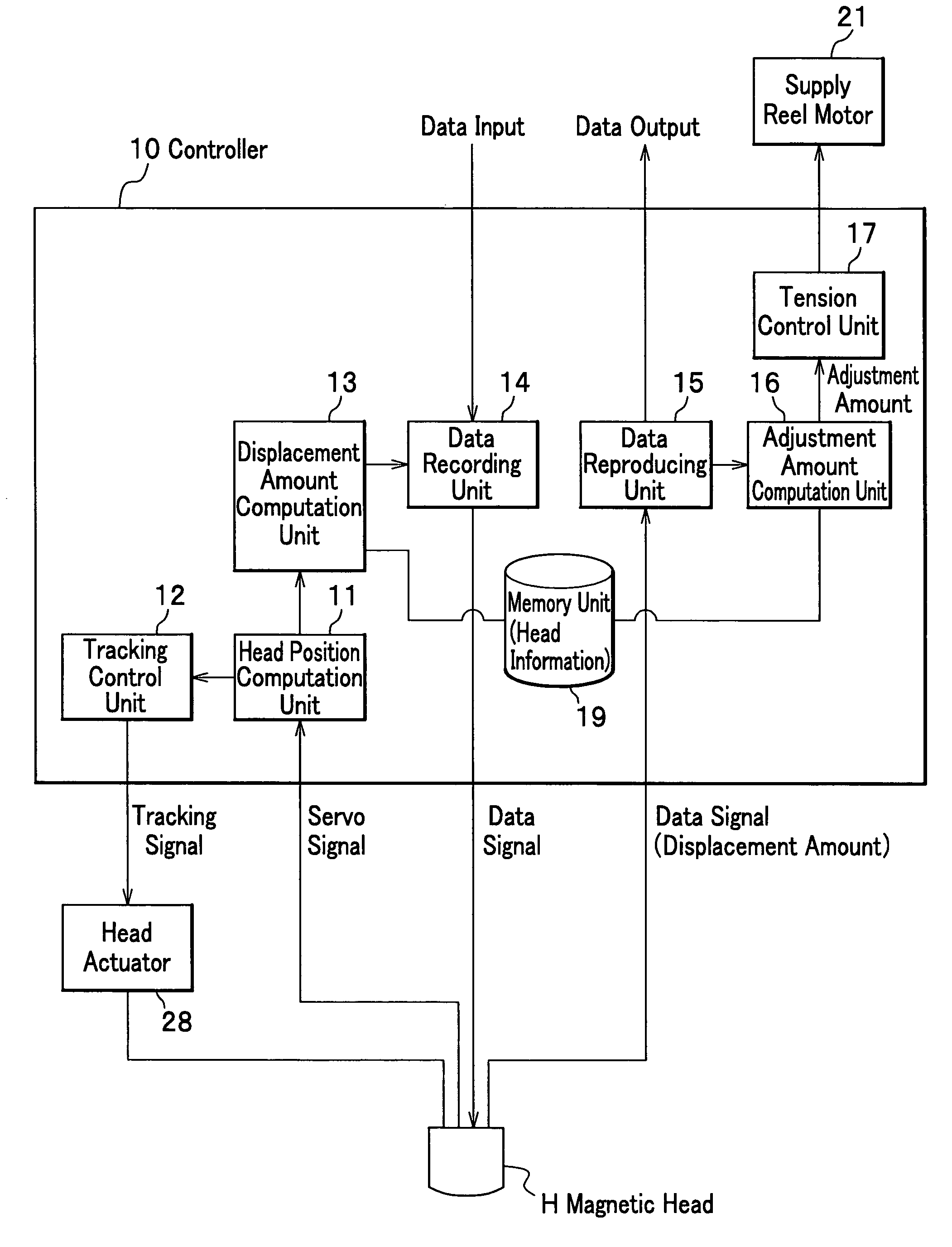
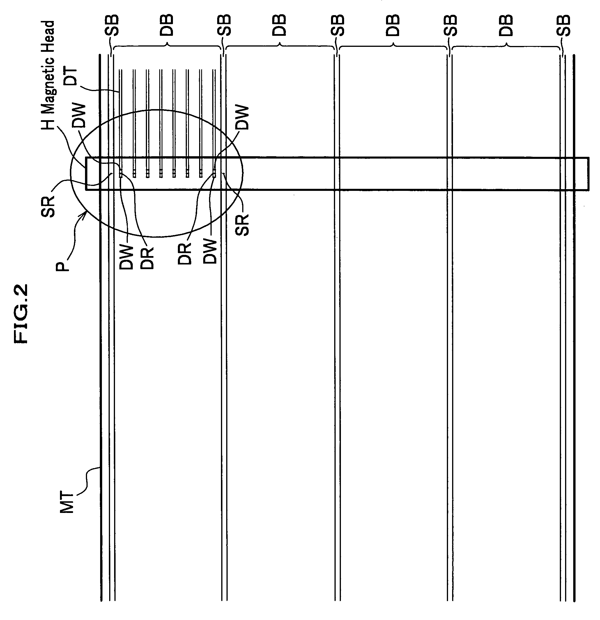
[0014]Because such a tape drive writes a displacement amount with at least a central data write element out of a plurality of data write elements while performing tracking control so as to distribute a difference between a pitch of a pair of servo read elements and that of a corresponding pair of servo bands to the pair of the servo read elements, the tape drive records the displacement amount on a central data track out of data tracks belonging to one data band. If so, the displacement amount results in being always recorded on the center of the data band, that is, being accurately recorded on the center of a pair of servo bands. Accordingly, If when reproducing data by another tape drive, tracking control of a data reproducing head is performed so as to distribute a difference between the pitch of the pair of the servo read elements and that of a pair of servo bands to the pair of the servo read elements, a central data read element certainly becomes on track; therefore a value of a displacement amount can be surely read.
[0017]In accordance with such a tape drive it is enabled to adjust a tape width by adjusting a tension thereof, to thereby repeat a similar condition in data recording, and to accurately position a data read element on a data track.
[0018]In addition, it is preferable in the tape drive that the data recording head and the data reproducing head are integrally formed. Thereby it becomes easy to match a positional relationship between a data write element and a data read element.

Problems solved by technology

Not limited to the magnetic tape, such a problem similarly occurs in an optical tape for recording data by light.

Method used


Image

  • Tape drive
  • Tape drive
  • Tape drive

Examples


Embodiment Construction

[0024]Here will be described an embodiment of the present invention in detail, referring to drawings as needed.

[0025]Hereinafter as an example of a tape drive will be described a magnetic tape drive for recording and reproducing data on a magnetic tape.

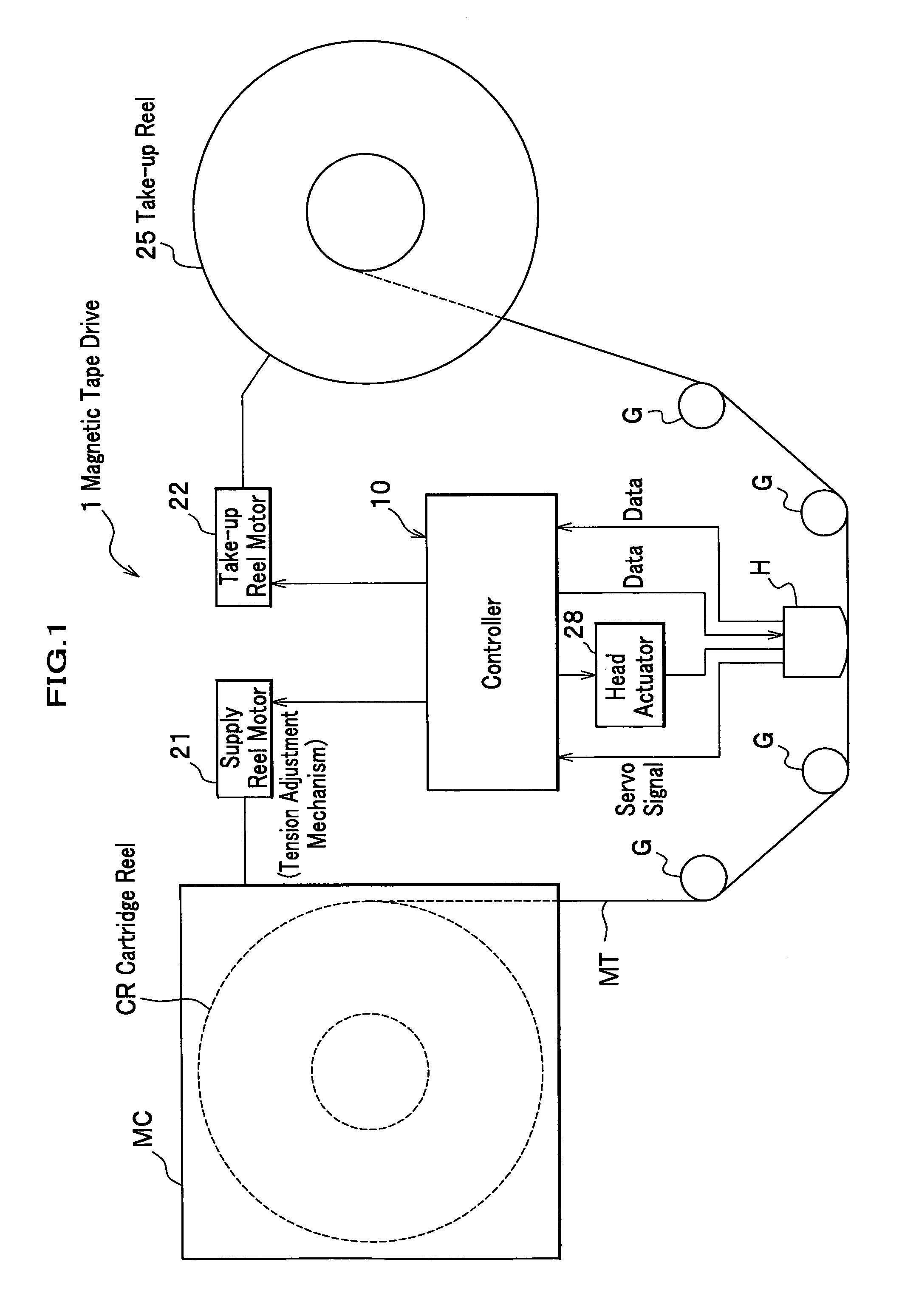
[0026]As shown in FIG. 1, a magnetic tape drive 1 related to the embodiment is an apparatus for pulling out a magnetic tape MT from a magnetic tape cartridge MC, and for recording and reproducing data by a magnetic head H.

[0027]The magnetic tape drive 1 mainly comprises a magnetic tape running system for running the magnetic tape MT and the magnetic head H arranged on a path where the magnetic tape MT runs.

[0028]The magnetic tape running system comprises a supply reel motor 21 for rotationally driving a cartridge reel CR within the magnetic tape cartridge MC; a take-up reel 25 for winding and rewinding the magnetic tape MT sent out from the cartridge reel CR; a take-up reel motor 22 for rotationally driving the take-up reel 25; a cont...


PUM

PropertyMeasurementUnit
thicknessaaaaaaaaaa
distanceaaaaaaaaaa
displacementaaaaaaaaaa

Abstract

A tape drive of the present invention records data on a tape having a plurality of servo bands, where a servo signal is recorded in advance along a longitudinal direction, and a data band containing a plurality of data tracks formed between each of the servo bands while tracking the tape, based on a servo signal: the tape drive comprises a tape running system for running the tape between two reels that can wind it; and a data recording head comprising a pair of servo read elements provided corresponding to the servo band, and data write elements provided plurally side by side between the pair of the servo read elements, wherein when recording the data, the tape drive writes a condition in recording, which is obtained by reading the servo signal with the servo read elements, in at least one of the data tracks with the data write elements.

Description

BACKGROUND OF THE INVENTION[0001]1. Field of the Invention[0002]The present invention relates to a magnetic tape system and a tape drive for data recording, and particularly, to a magnetic tape system and a tape drive that enable high density recording and reproducing of data highly densely recorded.[0003]2. Description of the Related Art[0004]These years, in a magnetic tape high density recording progresses, and there is one that has a data capacity of around 200 GB for a backup of a computer. Therefore, on the magnetic tape several hundreds of data tracks are formed in lateral directions thereof. Accordingly, a width of the data tracks is designed to be very narrow, and a distance of neighboring data tracks is also very narrow. Consequently, in order to make write / read elements of a magnetic head trace the data tracks, in such a magnetic tape drive a servo signal is written in the magnetic tape in advance, and servo-controls a position of the magnetic head (position in lateral dir...

Claims


Application Information

Patent Timeline
Patent Type & Authority Patents(United States)
IPC IPC(8): G11B5/584G11B15/18G11B20/20G11B15/43G11B15/02
CPCG11B5/584G11B15/026
Inventor NAKAO, TORU
Owner FUJIFILM CORP
Learn More