Optical fiber interconnect cabinets, termination modules and fiber connectivity management for the same

a technology of fiber connectivity and termination modules, applied in the field of optical fiber management, can solve problems such as not allowing access to the rear of the connector

Active Publication Date: 2006-11-28
COMMSCOPE TECH LLC
View PDF46 Cites 344 Cited by
  • Summary
  • Abstract
  • Description
  • Claims
  • Application Information

AI Technical Summary

Benefits of technology

[0011]In other embodiments of the present invention, the cable securing member is pivotally attached to the termination module to allow movement between the first position and the second position. The cable securing member may pivot about a neutral axis having an arc length for a cable secured therein that is substantially the same in the first and the second positions to limit loads on the cable secured therein during movement of the cable securing member between the first and second positions.

Problems solved by technology

These designs generally do not permit access to the rear of the connector without breaking a warranty seal and are designed for the central office environment.

Method used


Image

  • Optical fiber interconnect cabinets, termination modules and fiber connectivity management for the same
  • Optical fiber interconnect cabinets, termination modules and fiber connectivity management for the same
  • Optical fiber interconnect cabinets, termination modules and fiber connectivity management for the same

Examples


Embodiment Construction

[0033]The present invention now will be described more fully hereinafter with reference to the accompanying drawings, in which illustrative embodiments of the invention are shown. In the drawings, the relative sizes of regions or features may be exaggerated for clarity. This invention may, however, be embodied in many different forms and should not be construed as limited to the embodiments set forth herein; rather, these embodiments are provided so that this disclosure will be thorough and complete, and will fully convey the scope of the invention to those skilled in the art.

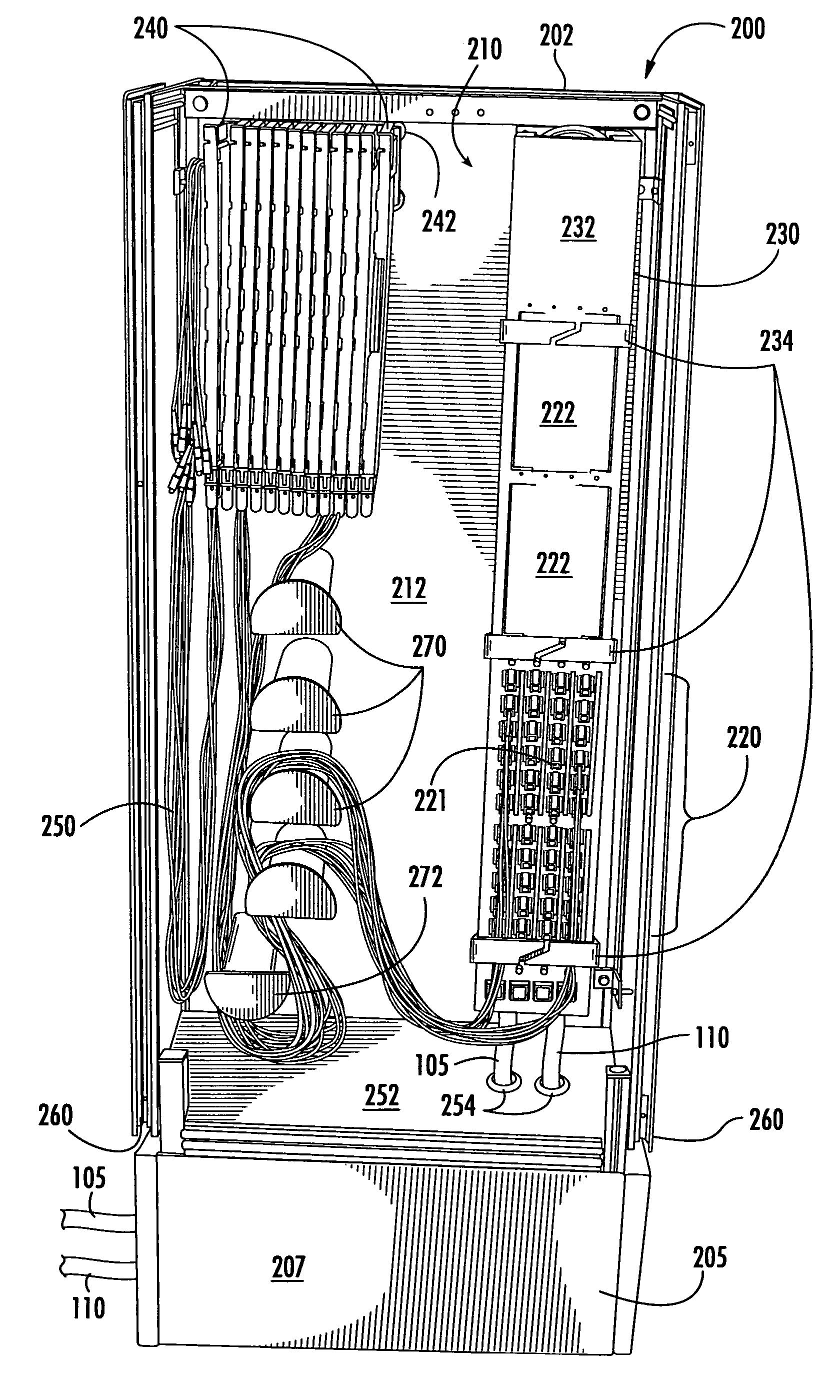
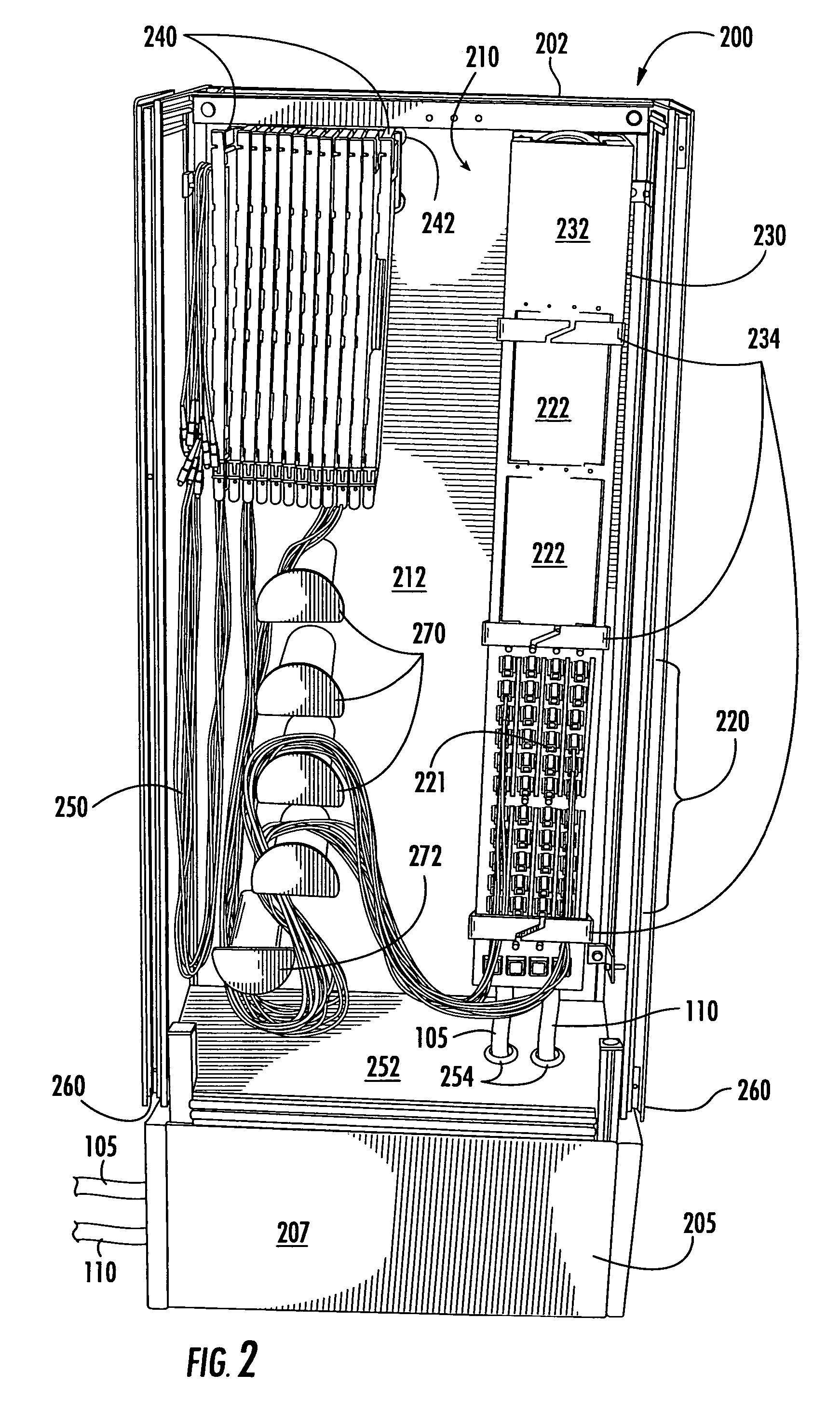
[0034]Some embodiments of the present invention utilize a multi-layer, fold down tray approach to support various functions, such as slack storage, pigtail to outside plant (OSP) cable splicing and angle down front patching. A termination module according to such embodiments may be designed in a modular fashion so that it can be used separately in a small pedestal or ganged together with other termination modul...


PUM


Abstract

Interconnect cabinets for optical fibers include an enclosure and a splitter and termination panel mounted in the enclosure. The splitter has a plurality of optical fiber connectorized pigtails extending therefrom. Each of the connectorized pigtails is associated with an optical fiber feeder cable to be coupled to a central office. The termination panel has a plurality of optical fiber connection members, ones of which are associated with respective subscriber locations. The connectorized pigtails have a cable length sufficient to allow connection to the plurality of connection members.

Description

RELATED APPLICATIONS[0001]The present application claims priority from U.S. Provisional Application No. 60 / 456,323, filed Mar. 20, 2003, the disclosure of which is hereby incorporated herein in its entirety by reference.BACKGROUND OF THE INVENTION[0002]The present invention relates to optical fiber management and, more particularly, to systems for connecting optical fibers.[0003]When providing services using an optical fiber network, it is generally necessary to add and drop subscribers over time. As a result, a variety of methods are provided for interconnecting subscriber locations with a central office connecting facility operated by an optical network provider. To improve the utilization of communication circuits within such a central office facility, interconnection cabinets, such as a centralized splitter cabinet (CSC) and / or centralized splitter cross-connect (CSX), may be provided as part of the outside plant (OSP) infrastructure of the optical fiber network. Doing so may al...

Claims


Application Information

Patent Timeline
Patent Type & Authority Patents(United States)
IPC IPC(8): G02B6/00G02B6/44
CPCG02B6/4452G02B6/4454G02B6/4441
Inventor ALLEN, BARRY W.DOWLING, DOUGLAS F.SMITH, JR., JACK A.
Owner COMMSCOPE TECH LLC
Why Eureka
Try Eureka