System for optimizing drilling in real time

a real-time optimization and drilling technology, applied in the field of rotary wellbore drilling, can solve the problem of not being able to account for all data when performing optimization techniques

Active Publication Date: 2006-11-28
SMITH INT INC
View PDF39 Cites 200 Cited by
  • Summary
  • Abstract
  • Description
  • Claims
  • Application Information

AI Technical Summary

Problems solved by technology

In the past, it has been impossible to account for all of the data when performing optimization techniques.

Method used


Image

  • System for optimizing drilling in real time
  • System for optimizing drilling in real time
  • System for optimizing drilling in real time

Examples


Embodiment Construction

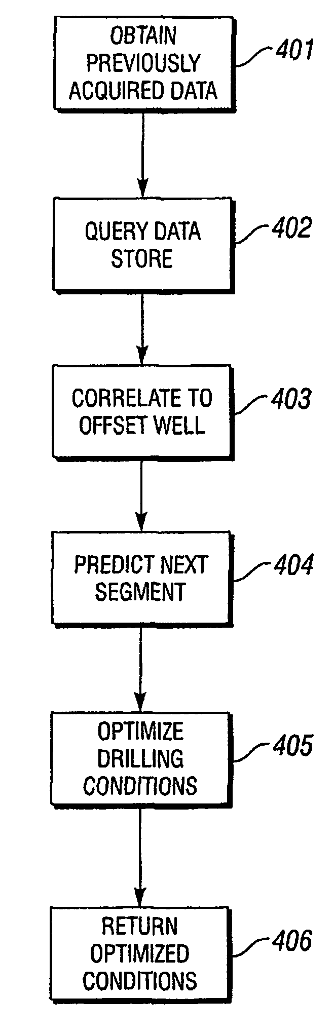
[0021]In one or more embodiments, the present invention relates to a method for optimizing drilling parameters based on data queried from a remote data store. In some embodiments, the optimization method is performed in real-time.

[0022]The following section contains definitions of several specific terms used in this disclosure. These definitions are intended to clarify the meaning of the terms used herein. It is believed that the terms are used in a manner consistent with their ordinary meaning, but the definitions are nonetheless specified here for clarity.

[0023]The term “real-time” is defined in the MCGRAW-HILL DICTIONARY OF SCIENTIFIC AND TECHNICAL TERMS (6th ed., 2003) on page 1758. “Real-time” pertains to a data-processing system that controls an ongoing process and delivers its outputs (or controls its inputs) not later than the time when these are needed for effective control. In this disclosure, “in real-time” means that optimized drilling parameters for an upcoming segment ...


PUM


Abstract

A method for optimizing drilling parameters includes obtaining previously acquired data, querying a remote data store for current well data, determining optimized drilling parameters, and returning optimized parameters for a next segment to the remote data store. Determining optimized drilling parameters may include correlating the current well data to the previously acquired data, predicting drilling conditions for the next segment, and optimizing drilling parameters for the next segment.

Description

BACKGROUND OF INVENTION[0001]1. Field of the Invention[0002]The present invention is related generally to the field of rotary wellbore drilling. More specifically, the invention relates to methods for optimizing values of drilling variables, or parameters, in real time to improve or optimize drilling performance based on drilling objectives.[0003]2. Background Art[0004]Wellbore drilling, which is used, for example, in petroleum exploration and production, includes rotating a drill bit while applying axial force to the drill bit. The rotation and the axial force are typically provided by equipment at the surface that includes a drilling “rig.” The rig includes various devices to lift, rotate, and control segments of drill pipe, which ultimately connect the drill bit to the equipment on the rig. The drill pipe provides a hydraulic passage through which drilling fluid is pumped. The drilling fluid discharges through selected-size orifices in the bit (“jets”) for the purposes of cooling...

Claims


Application Information

Patent Timeline
Patent Type & Authority Patents(United States)
IPC IPC(8): E21B44/00E21B41/00
CPCE21B44/00E21B44/005E21B2200/22
Inventor MORAN, DAVID P.
Owner SMITH INT INC
Why Eureka
Try Eureka